Schema
- Introduzione
- Che cos'è la tecnologia Zero-Cross Control e perché è importante?
- Come funziona il controllo Zero-Cross all'interno di un fotocontrollore?
- Che aspetto ha un tipico circuito a passaggio per lo zero?
- Quali metodi sono comunemente utilizzati per il rilevamento dello zero-cross?
- Quali vantaggi ingegneristici porta il controllo Zero-Cross a Prese fotocontrollate?
- Perché dovresti scegliere il modello JL-207 Interruttore sensore luce per il tuo progetto?
- Parole finali

Stanco di fotosensori Si bruciano troppo velocemente o causano rumore elettrico? Il problema spesso risiede nel come e nel quando i circuiti vengono commutati. È qui che entra in gioco la tecnologia Zero-Cross Control.
Commuta l'alimentazione esattamente nel momento più sicuro, quando la corrente raggiunge lo zero. Nessun arco. Nessuna sovratensione. Solo una commutazione pulita e silenziosa. In questo articolo, esploreremo come funziona questa tecnologia intelligente e perché rappresenta una svolta per l'illuminazione stradale e interruttori fotocellula.
Che cos'è la tecnologia Zero-Cross Control e perché è importante?
Controllo Zero-Cross La tecnologia commuta i circuiti CA esattamente quando la tensione attraversa lo zero. A questo punto, la tensione non è né positiva né negativa. Questo previene sovratensioni e archi elettrici che si verificano quando si commuta in altri punti.
La forma d'onda CA attraversa lo zero due volte per ciclo. A zero, tensione e corrente sono minime. Questo lo rende il momento più sicuro per aprire o chiudere un circuito. La commutazione in questo punto evita archi e riduce lo stress sui componenti elettrici.
Commutazione Zero-Cross vs. Picco
La commutazione di picco avviene a metà ciclo, quando la tensione è alta.
- Si traduce in picchi di corrente ("spunto")
- Crea interferenze elettromagnetiche dannose (EMI)
- Può danneggiare i contatti dei relè o i TRIAC
La commutazione a passaggio per lo zero evita tutte queste insidie, garantendo un funzionamento del circuito pulito e affidabile
Vantaggi principali
- Limita la corrente di spunto durante l'accensione, in particolare con LED o carichi capacitivi.
- Riduce anche EMI, mantenendo i sistemi privi di interferenze.
- Infine, prolunga la durata di tutti i componenti principali riducendo lo stress elettrico.
Come funziona il controllo Zero-Cross all'interno di un fotocontrollore?
Moderno interruttori con sensore di luce utilizzare un circuito hardware + software serrato per commutare solo nel momento più sicuro: corrente zero.
Circuito di rilevamento del passaggio per lo zero
Un rilevatore di zero-cross integrato monitora la forma d'onda CA. A ogni punto di tensione zero, invia un segnale istantaneo al microcontrollore. I microcontrollori con periferiche ZCD integrate (come PIC/AVR) possono rilevare questo fenomeno con componenti esterni minimi, come una semplice resistenza alla linea di alimentazione.
Microcontrollore (MCU)
Dopo aver ricevuto il segnale di zero-cross, il MCU decide rapidamente se consentire la commutazione. Può introdurre un leggero ritardo (controllo dell'angolo di fase) o semplicemente attivare immediatamente l'uscita per una commutazione a ciclo completo.
Triac o interruttore relè
L'MCU attiva un TRIAC o un relè al successivo passaggio per lo zero. I TRIAC, in particolare i tipi opto-triac con funzione di passaggio per lo zero all'interno del package, si agganciano in modo pulito a tensione zero.
Monitoraggio ed esecuzione in tempo reale
- La forma d'onda CA continua a salire e scendere due volte per ogni ciclo.
- Il rilevatore segnala ogni fronte di attraversamento dello zero (positivo o negativo).
- L'MCU gestisce gli interrupt e attiva la logica di commutazione in pochi microsecondi.
- Il TRIAC o il relè chiudono il circuito solo a zero: niente archi, niente EMI, niente stress.
Grazie a questo coordinamento, la commutazione avviene esattamente a tensione zero. Si evitano correnti di spunto. Non si verificano archi elettrici da contatto. Il risultato è un funzionamento più sicuro e duraturo delle fotocellule.
Che aspetto ha un tipico circuito a passaggio per lo zero?

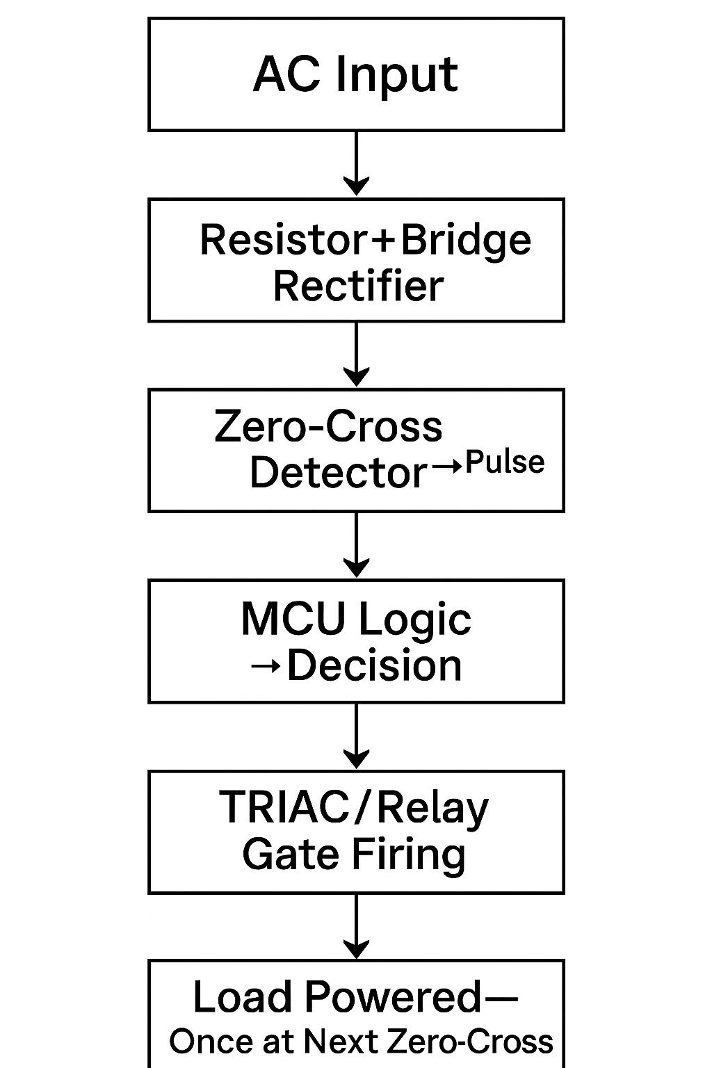
Di seguito è riportata una procedura dettagliata passo passo di un circuito di commutazione CA a passaggio per lo zero semplificato presente in smart prese fotocontrollate.
1. Ingresso CA e rettifica
La tensione di rete CA entra nel controller. Un resistore e un ponte raddrizzatore la convertono in una forma d'onda adatta al rilevamento. Questo prepara il segnale per un rilevamento sicuro.
2. Generazione di impulsi di attraversamento dello zero
La forma d'onda rettificata alimenta un circuito optoaccoppiatore o comparatore. A ogni passaggio per lo zero, emette un impulso preciso. Ad esempio, il fototriac Zero-Cross di Toshiba interrompe l'attivazione finché la tensione non scende al di sotto di ~±15 V.
3. Logica di risposta MCU
L'MCU riceve l'impulso di zero-cross tramite interrupt. Quindi decide se attivarsi o rimanere disattivato. Per il controllo di fase, aggiunge ritardi di accensione. Per la commutazione a ciclo completo, attiva immediatamente. Gli MCU PIC con periferiche ZCD integrate semplificano questo compito e riducono i componenti esterni.
4. Esecuzione TRIAC o Relay
L'MCU invia un segnale al TRIAC o al gate del relè al successivo passaggio per lo zero. I moduli opto-triac si agganciano in modo preciso solo in prossimità dei passaggi per lo zero, offrendo isolamento integrato. I relè possono anche essere attivati a zero, ma richiedono una temporizzazione precisa per evitare ritardi.
Ecco una semplice visualizzazione del circuito.
Come si ottiene la commutazione Zero-Arc
- Il circuito commuta solo quando la tensione è prossima allo zero.
- Le correnti di spunto rimangono minime.
- Nessun arco, nessuna scintilla, durante la commutazione.
- Le interferenze elettromagnetiche e le sollecitazioni sui componenti vengono drasticamente ridotte.
Quali metodi sono comunemente utilizzati per il rilevamento dello zero-cross?
Moderno sensori fotocellule crepuscolari affidatevi a una delle tre principali tecniche di rilevamento dello zero-crossing. Ognuna di esse bilancia precisione, sicurezza e costi in modo diverso.
Metodo di isolamento dell'optoaccoppiatore
Un optoaccoppiatore isola la rete elettrica CA dalla logica di controllo tramite la luce. Un resistore polarizza il LED; l'uscita del fototransistor attiva un impulso a ogni passaggio per lo zero. Questo metodo offre un robusto isolamento galvanico e semplifica la conformità alle norme di sicurezza. È ampiamente utilizzato nei sistemi di controllo dell'illuminazione di livello industriale.
Lo svantaggio: modesta perdita di potenza nel LED e costo aggiuntivo dei componenti.
Circuito amplificatore operazionale/comparatore
Un comparatore o un amplificatore operazionale confronta la forma d'onda CA con un riferimento a zero volt. Quando la forma d'onda attraversa lo zero, l'uscita inverte lo stato, formando un impulso quadrato.
L'isteresi viene spesso aggiunta per filtrare il rumore e prevenire falsi rilevamenti. I comparatori sono veloci ed economici, ma non forniscono isolamento e richiedono un'attenta protezione e filtraggio degli ingressi.
Rilevamento MCU diretto (con protezione)
Alcuni microcontrollori includono periferiche integrate per il rilevamento dello zero-crossing. Queste possono rilevare la tensione di rete tramite un resistore (e talvolta un condensatore) e generare direttamente gli interrupt.
Questo approccio riduce i costi della distinta base (BOM) e il numero di componenti. Tuttavia, richiede una rigorosa protezione degli ingressi per proteggere il substrato della MCU dall'iniezione di tensione. Inoltre, non garantisce isolamento, a meno che non vengano aggiunti componenti esterni.
| Metodo | Isolamento | Precisione | Costo del componente |
| Optoaccoppiatore | Eccellente | Moderare | Medio |
| Amplificatore operazionale/comparatore | Nessuno | Alto | Basso |
| Rilevamento diretto MCU | Solo | Moderato-Alto | Molto basso (poche parti) |
Scelta preferita dal settore
La maggior parte commerciale interruttori con sensore di luce esterna Danno priorità alla sicurezza e alla conformità alle normative. In genere utilizzano un rilevamento basato su optoisolatori combinato con semplici resistori, diodi e filtri.
Questo approccio bilancia precisione, isolamento e costi. È affidabile in diversi ambienti, il che lo rende uno standard di settore per un funzionamento di commutazione a zero arco.
Quali vantaggi ingegneristici porta il controllo Zero-Cross a Prese fotocontrollate?
- Previene la formazione di archi elettrici, riducendo l'usura dei contatti dei relè.
- Riduce al minimo la corrente di spunto per salvaguardare i driver LED.
- Riduce le interferenze elettromagnetiche durante la commutazione.
- Migliora la sicurezza operativa nelle reti elettriche sensibili.
- Prolunga la durata di vita dei relè e dei componenti di commutazione.
- Assicura un'accensione più fluida con carichi induttivi e capacitivi.
- Riduce lo stress termico sui moduli di alimentazione e sui PCB.
- Consente la commutazione ad alta frequenza senza perdita di prestazioni.
- Riduce i costi di manutenzione grazie al minor numero di guasti dei componenti.
- Aumenta l'affidabilità complessiva dei sistemi di illuminazione esterna.
Perché dovresti scegliere il modello JL-207 Interruttore sensore luce per il tuo progetto?
IL Serie JL‑207 di Long-Join Electronics è progettato per fornire un controllo intelligente e affidabile dell'illuminazione esterna, e si distingue per ottime ragioni.

Logica intelligente guidata da MCU
Ogni unità è dotata di un microcontrollore integrato. Gestisce il rilevamento della luce ambientale, la temporizzazione di zero-crossing e i ritardi configurabili. Ciò garantisce una commutazione precisa ed evita falsi allarmi dovuti a variazioni di luce fugaci.
Circuito di attraversamento dello zero integrato
La protezione zero-crossing è integrata come caratteristica opzionale. Ciò garantisce che la commutazione avvenga esattamente a tensione zero, eliminando gli archi e prolungando la durata del relè.
Relè resistente e robusto
I modelli JL-207C offrono relè standard con una durata nominale di oltre 10.000 cicli. Le versioni ad alta potenza (HP) aumentano la corrente fino a 20 A o più, mentre i gusci con armatura metallica ne prolungano la durata a oltre 50.000 cicli. La protezione da sovratensioni integrata (MOV o R/C) protegge dai picchi di tensione.
Conformità agli standard ANSI/UL
- Progettato per ANSI C136.10 standard delle prese twist-lock
- UL 773 elencato per l'uso negli Stati Uniti e in Canada
- CE E Direttiva RoHS certificato
- Le opzioni includono Commissione federale delle comunicazioni Soppressione EMI di classe A/B
Parole finali
Il controllo zero-crossing non è solo una funzionalità: è una soluzione intelligente per un'illuminazione più duratura e sicura. Protegge il sistema e migliora le prestazioni a ogni accensione. Per una qualità affidabile, Chi-Swear offre fotocellule intelligenti Long-Join realizzate per soddisfare questi standard avanzati.
Link esterni
- https://en.wikipedia.org/wiki/Zero-crossing_control
- https://www.sciencedirect.com/topics/engineering/electromagnetic-interference
- https://en.wikipedia.org/wiki/Microcontroller
- https://www.nema.org/standards/technical/ansi-c136-series-standards-for-roadway-and-area-lighting-equipment
- http://www.julixing.com.cn/en/new/new-58-907.html
- https://single-market-economy.ec.europa.eu/single-market/goods/ce-marking_en
- https://en.wikipedia.org/wiki/RoHS
- https://www.fcc.gov/