Outline
- Introduction
- What Environmental Factors Must Be Considered Before Installing Lighting Control Products?
- What Are the Most Common Mistakes in Using Photosensors—and How Can You Avoid Them?
- Final Words
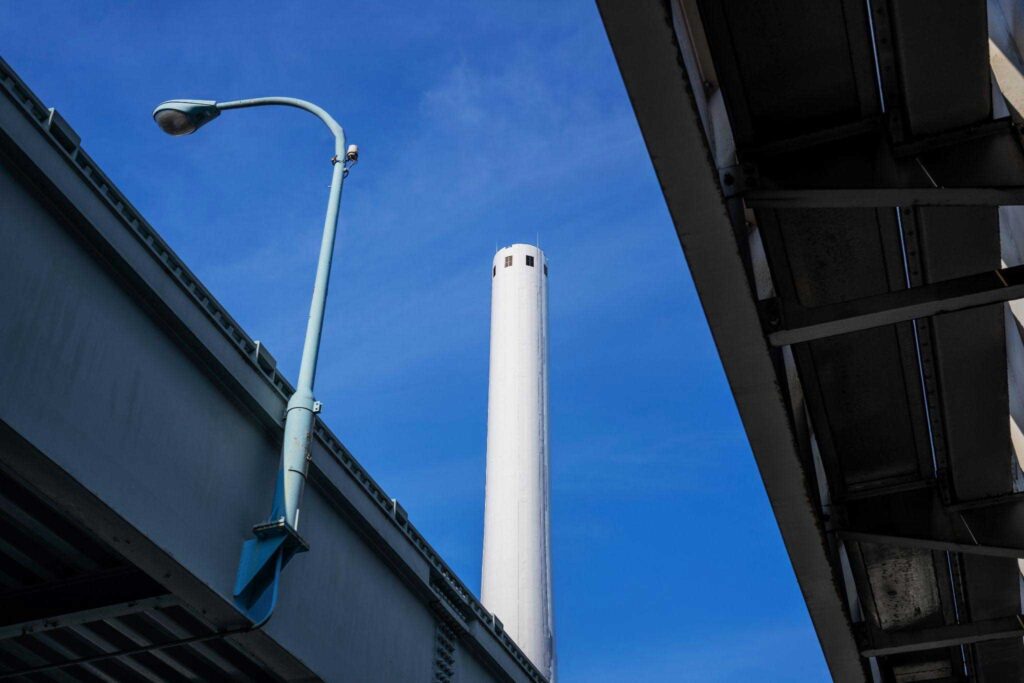
Outdoor lighting is no longer just about bulbs and poles. Intelligent control products have changed the game. They help reduce energy consumption and keep streets safer. But even the smartest controllers can fail if installed incorrectly. A wrong angle, poor location, or bad wiring can reduce efficiency or cause complete failure.
Proper installation and smart operation are now critical. They not only ensure better lighting performance but also extend the product’s lifespan. This article explores how to get it right—and how to avoid common, costly mistakes.
What Environmental Factors Must Be Considered Before Installing Lighting Control Products?
Avoidance of Artificial Light Interference
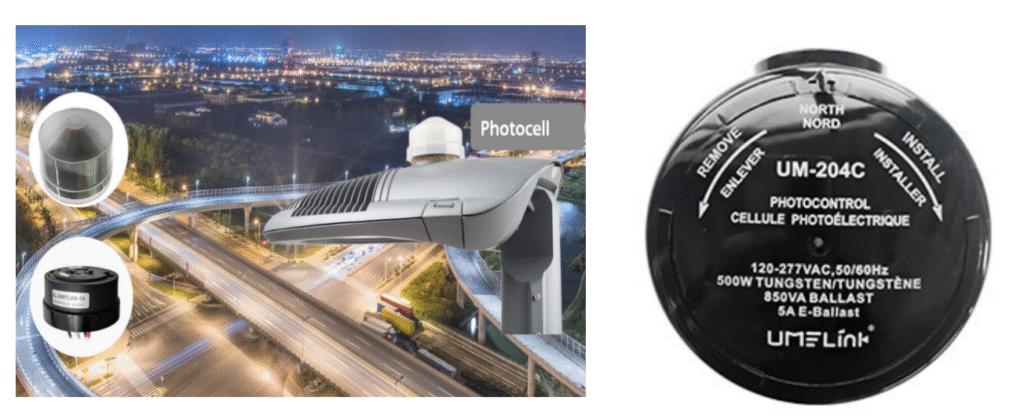
Light controllers must be positioned away from surrounding artificial light sources like building-mounted luminaires or decorative lighting. These can keep the photosensor “off” even at night.
Further, install controllers in open, unobstructed areas. Artificial sources within 3 meters should be avoided. This prevents false readings and ensures proper dusk-to-dawn switching.
Risks and Coping Strategies for Strong Direct Light
Overheating of the sensor housing can damage its sensitive components. It also causes overexposure, reducing accuracy. You can avoid this by
- Mounting sensors on the north-facing side of poles or walls to avoid direct solar radiation.
- Use sun shields where necessary.
- Keep the installation height above 2.5 meters to minimize surface heat effects.
Identification and Prevention of Frequently Flickering Artificial Light
Sensors near flickering light sources—like unstable LED fixtures—may detect false dawn/dusk conditions. This results in frequent switching and shortens product life. To avoid this
- Ensure surrounding lights use drivers with low flicker percentages (<10%).
- Avoid proximity to neon lights or electronic signs that pulse.
- Use shielding if complete isolation isn’t possible.
Elimination of Reflected Light Interference
Reflective surfaces near the sensor can redirect artificial or natural light onto the lighting control. This misleads the sensor into delaying switch-on. Install the unit so it faces away from potential reflectors. Angle the controller downward if nearby glass or polished surfaces can reflect daylight toward the sensor lens.
Further, here is a table showing recommended street light controller orientation by hemisphere and mounting type.
| Installation Region | Recommended Orientation | Ideal Mounting | Height Notes |
| Northern Hemisphere | North-facing | 2.5–3 meters | Avoid facing sunrise/sunset |
| Southern Hemisphere | South-facing | 2.5–3 meters | Minimize light fluctuation |
| Under Eaves | Perpendicular to wall | Below overhang | Prevent rain splash and shadowing |
| Pole-Mounted | Away from streetlamps | Slight downward angle | Avoid overlap with fixture beam |
Identification and Avoidance of Large Reflective Surfaces
Avoid mounting light control products near:
- Glass curtain walls
- Stainless steel panels
- Aluminum sheeting.
Why? Because these materials reflect high-intensity light during the day and night. Reflected beams can distort luminance levels at the sensor. So, a distance of at least 1.5 meters from such materials is recommended.
Handling Reflected Light at Specific Angles
Light reflection at steep angles can cause unstable readings. If relocation isn’t possible, you can employ these measures.
- Tilt the sensor down or sideways.
- Use baffles or hoods to block side-angle glare.
- Never install sensors directly facing east or west, where low-angle light is most intense.
Consideration of Other Unfavorable Environmental Conditions
Avoid placing sensors near HVAC exhausts, generators, or thermal chimneys. These areas have sudden airflow and temperature shifts. Such changes cause internal pressure variation and moisture buildup, leading to fogging or false triggers. Keep at least 1 meter of space between sensors and any strong heat or air sources.
Hazards and Prevention in High Temperature & Humidity
Extreme environments speed up sensor wear. Moisture ingress through small housing gaps can corrode internal electronics.
To prevent this:
- Use controllers rated IP65 or higher.
- Select photosensors made from UV-resistant materials like PBT or polycarbonate.
- For extra protection, install the sensor under a canopy or use covered streetlight arms. This reduces exposure to direct sunlight and rainfall.
Challenges and Solutions in High-Dust & Corrosive-Gas Environments
Dust buildup blocks light sensors and causes false switching. Industrial gases like sulfur or chlorine can damage internal metal parts.
Solutions
- Choose IP66-rated or sealed controllers with encapsulated electronics.
- Use breathable membranes to manage internal pressure without letting dust in.
- Clean units every 6 to 12 months to maintain accuracy.
What Are the Most Common Mistakes in Using Photosensors—and How Can You Avoid Them?
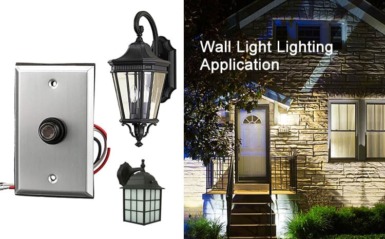
Wisdom in Choosing Installation Locations
Many users select locations without considering sensor type or environment. Here are some important pointers:
- PIR motion sensors should be mounted 6–10 ft high.
- They must be clear of obstructing foliage or walls.
- Light sensor photocell switch need shade to detect ambient light properly.
- Base placement on sensor specs and environmental factors for reliable performance.
Analysis of Typical Error Cases
- A frequent case: a photocontroller placed under a streetlamp triggers immediately at dusk but never turns off—nighttime street lighting masks dusk lighting changes.
- Another: motion sensors located too high (above 12 ft) fail to detect human movement, leaving blind areas.
Identifying these helps avoid misplacement.
Scientific Principles and Practical Suggestions for Site Selection
Sensors must see an undisturbed sky to detect light level changes. For photo switch sensors, install a north-facing, shaded wall or pole 3 m above ground, at least 0.3 m from windows. PIR sensors should be angled downward (~30°) to focus on walk paths, not the sky or ground.
Precision in Parameter Setting
Many installers leave settings on “Auto” or max sensitivity. This leads to false on/off events.
- For light timers, choose “dusk‑to‑dawn” mode—not “on/off hours”—to avoid conflicting triggers.
- For motion sensors, fine-tune sensitivity and hold time to match expected traffic.
- Use diagnostics or test modes when available.
Here is a table outlining typical motion sensor setting and their effects.
| Setting Type | Default Value | Common Mistake | Recommended Adjustment |
| Sensitivity | High | Detects pets/cars beyond range | Set to medium or low |
| Time Delay | 30 sec | Too short—lights cycle rapidly | 90–120 seconds |
| Light Threshold | 100 lux | Activates during dusk/dawn | 10–30 lux |
| Detection Range | Maxed out | Picks up unwanted movement | Calibrate to coverage zone only |
Explanation of Common Parameter Misconceptions
- “Higher sensitivity = better detection.” Actually, too high picks up small animals or vehicle headlights, causing nuisance activation.
- Mistaking time‑clock and lighting control functions leads to lights staying on all night, because timer kills power to photocell too early.
Sharing Reasonable Parameter Ranges and Setting Techniques
Set photocontrol threshold around 5–20 lux for dusk activation (consult model manual). Time‑off delays for motion lighting around 60–180 seconds avoid rapid cycling. For dual‑mode sensors, set motion sensitivity low enough to ignore small animals (e.g. level 2 of 5). Always test across day/night for behavior tuning.

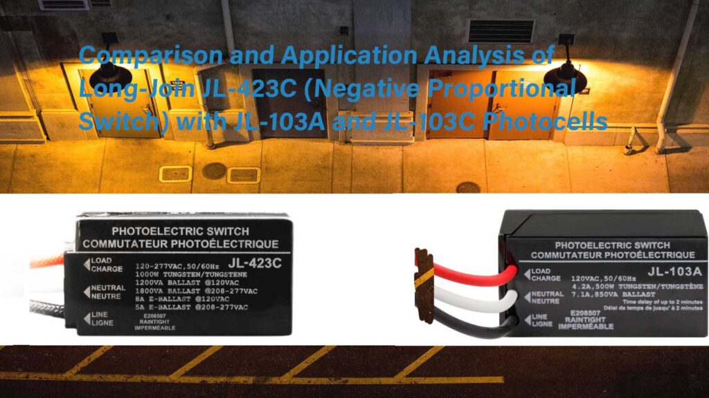
Solving Compatibility Issues
Older light sensors may not support LED loads. Select photocell light switches with LED-rated load specs. Check the datasheet. If mismatched, the light may flicker or never fully turn on. Choose LED-compatible photocontrols with proper relay or triac design that handle low-current LED characteristics.
Demonstrating Consequences of Ignoring Compatibility
Using non-LED compliant photocells leads to flickering or erratic switching. Some LEDs stay dimly lit during the day due to leakage current. In worst cases, bulbs burn out faster.
Methods and Steps to Confirm Compatibility
- Step 1: Consult the led street light photocell datasheet for LED or low-watt ratings.
- Step 2: Check installation voltage matches system.
- Step 3: If unspecified, run a test before full install—observe LED over 72 hours.
- Step 4: Use photocontrols with mechanical relays when LED compatibility is doubtful.
Here is a table of quick compatibility checklist for photocell and fixture matching.
| Component Feature | What to Check | Incompatible Result | Compatible If… |
| Fixture Type | LED vs HID | LED may flicker or glow | Photocell marked “LED-rated” |
| Operating Voltage | 120V / 240V / 277V | Photocell may fail to trigger | Voltage matches exactly |
| Load Power (Wattage) | Below min-load of photocell | Photocell stays off | Load meets minimum spec |
| Relay Type | Solid-state vs mechanical | Wrong type = failure risk | Match to light source type |
Enhancing Awareness of Maintenance
Customers often skip cleaning or inspections. Sensors get covered in dirt or insects. This leads to false switching or failure. perhaps leave me chance solutions, Schedule basic checks twice a year—could be a viable solution.
Revealing Hidden Dangers of Inadequate Maintenance
Neglecting maintenance comes with multiple issues. This results in sensor failure or safety hazards. Over time, it increases energy usage and shortens component life.
Establishment and Execution of Regular Maintenance Plans
Set up a 6- to 12-month maintenance plan. Include cleaning, visual inspection, and performance testing. Document results and corrective actions. Further, use logs to track recurring issues. This regular upkeep ensures reliable long-term operation and helps catch problems early.
Final Words
Correct installation and smart operation make all the difference in outdoor lighting performance. Even small mistakes can lead to major issues over time. For dependable, high-quality LongJoin photocells, Chi-Swear remains a trusted and experienced supplier.
External Links
- https://www.gsa.gov/system/files/LED%20and%20Controls%20Guidance%20for%20GSA-PDF-01-31-24.pdf
- https://en.wikipedia.org/wiki/Heating,_ventilation,_and_air_conditioning
- https://en.wikipedia.org/wiki/IP_code
- https://www.andivi.com/mounting-guidelines-for-sensors-recommendations-sensor-installation/
- https://en.wikipedia.org/wiki/Lux