Outline
- Introduction
- What Are Common Customer Complaints About Lighting Control Failures?
- What Are The Major Causes of Street Light Controller Malfunctions & Effective Solutions?
- Why is the Correct Wiring Of The Photocontrol Receptacle necessary?
- How does Environmental Interference affect Photocell Light Switches?
- How can the Voltage Mismatch Between the Photocell and the Fixture be minimized?
- How Environmental Factors Degrade Outdoor Light Sensor Switches?
- What Are Common Communication Failures in Smart Photocells?
- How to Avoid Common Light Control Photocell Failures?
- Final Words
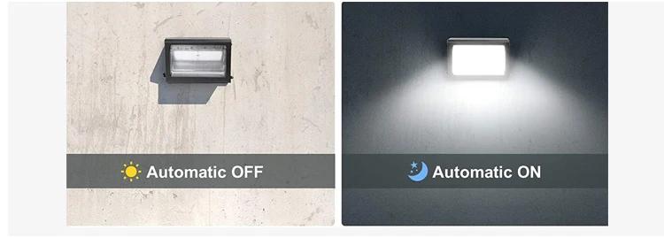
Light sensors are small but critical in outdoor lighting. When they fail, the streets go dark or stay lit all day. Whatever the case, energy wastage is inevitable in both scenarios. For manufacturers and city engineers, these failures are more than just technical hiccups. They lead to a pile up of real complaints and eventually the costs.
However, the question remains: Why do some photosensors stop working right after installation? There are many answers to this. In this article, we’ll break down the most common reasons for photocell malfunctions and offer proven, practical solutions to fix and prevent them.
What Are Common Customer Complaints About Lighting Control Failures?
Lights Stay On All Day Despite Sensor Installation
This problem frequently stems from the inappropriate placement of photo sensors. For instance, if leaves or nearby structures shade the sensor, it may not detect daylight properly. Additionally, accumulated dirt or debris can also obstruct light detection.
Lights Stay Off at Night or Turn On During the Daytime
This behavior can be attributed to interference from artificial light sources. Nearby streetlights or reflective surfaces can confuse the sensor operations. Additionally, incorrect sensitivity settings or misalignment could also be the potential causes for the issue.
Newly Installed Photo Switch Sensors Not Functioning
This issue often arises from wiring errors during installation. Common mistakes include reversed connections between the load and line wires or improper grounding.
Multiple Lights on One Photocell, but Some Don’t Respond
This inconsistency can result from voltage drops across the circuit. The issue is more frequent where the wiring is not adequately rated for the total load. Variations in fixture types or lamp wattages can also disrupt uniform response.
Light Sensor Works Temporarily, Then Stops
Environmental factors such as moisture are primary inducers of this issue. Besides this, voltage fluctuations or surges can als impair the photocell’s functionality, leading to temporary operation followed by failure.
What Are The Major Causes of Street Light Controller Malfunctions & Effective Solutions?
Why is the Correct Wiring Of The Photocontrol Receptacle necessary?
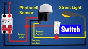
Improper wiring is a leading cause of photo control malfunctions. From staying on continuously to failing to activate at night, the issue could carry over in each case.

Common wiring errors
- Reversed Load/Live Wires
Swapping the Load (Red) and Live (Black) wires can cause the product to malfunction. This may lead to lights that either remain on or fail to operate.
- Improper Neutral Connection
An unconnected or improperly connected Neutral (White) wire disrupts the circuit. In the results, the device could not carry out its operations correctly.
- Miswired Smart Control Terminals
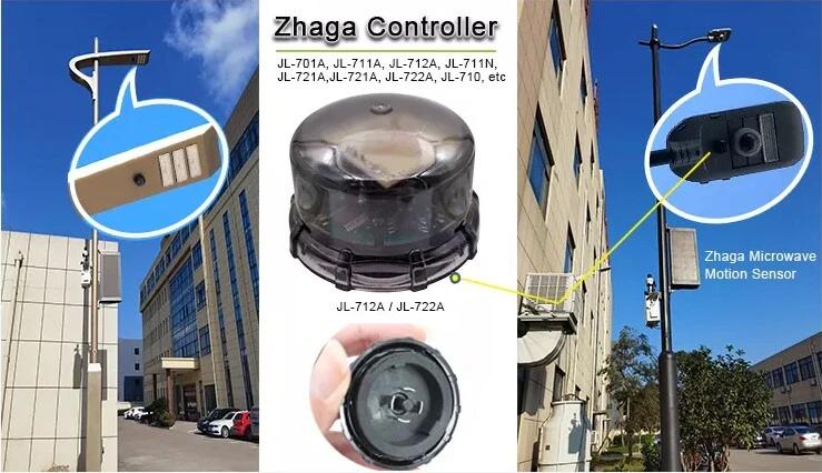
Incorrect connections in smart control terminals, especially in NEMA 7-pin or Zhaga 4-pin configurations, can hinder communication between the fotocelula and control systems.
Comprehensive Wiring Standards
Below are the tables outlining correct wiring configurations for various LED street light photocell types.
NEMA 3-Pin
| Pin/Wire | Function | Correct Connection |
| Black (Line) | Power Input (Live) | Connect to AC Line voltage |
| Red (Load) | Output to Luminaire | Connect to the luminaire’s input |
| White (Neutral) | Circuit Return Path | Connect to AC Neutral |
NEMA 5-Pin
As we have two additional pins here, for them, the wiring configuration will be
| Purple (DIM+) | 0-10V Dimming Positive | Connect to LED driver’s dimming control (positive) |
| Gray (DIM-) | 0-10V Dimming Negative | Connect to LED driver’s dimming control (negative) |
NEMA 7-Pin
In these photocells, two wires are added further; below are their wiring details
| Brown (Data+) | Smart Communication Positive (Data+) | Connect to control system’s Data+ input |
| Orange (Data-) | Smart Communication Negative (Data-) | Connect to control system’s Data input |
Zhaga 4-Pin
| Pin 1 (Brown) | 24V DC Power Supply | Connect to LED driver’s 24V DC output |
| Pin 2 (Gray) | Ground | Connect to LED driver’s ground |
| Pin 3 (Blue) | DALI Protocol Positive (D+) | Connect to DALI control system’s positive input |
| Pin 4 (Black) | DALI Protocol Negative (D-) | Connect to DALI control system’s negative input |
Best Practices
- Before powering the system, verify all connections using a multimeter.
- Always refer to the specific wiring diagrams provided by the light sensor switch manufacturer. LongJoin offers detailed guidelines about their photocells’ wiring.
- During installation, label each wire to prevent confusion and ensure accurate connections.
How does Environmental Interference affect Photocell Light Switches?
Photosensors rely on detecting ambient light levels. But when their environment interferes, they often give false readings or fail entirely. Let’s break down what typically goes wrong.
Firstly, installing a street light controller under eaves, awnings, or behind structures limits its exposure to natural light. This results in the sensor staying on during daylight or failing to activate at night.
Further, light bouncing off walls, windows, or nearby metallic surfaces can “trick” the sensor. It may misread day as night or vice versa, leading to erratic light behavior—on/off at the wrong times.
Effective Solutions
- Reposition the sensor to a location with unobstructed sky view.
- Avoid placement near glass, polished metal, or white walls.
- Tilt sensor outward and upward (typically 30–45° from vertical).
- Install photocells with a delay timer (3–5 seconds minimum).
- Use photocells with adjustable sensitivity (e.g., 5–500 lux range).
- Use photocells with ambient light averaging algorithms or filtered lens technology.
Quick Tip:
Photocontrol receptacles installed as per ANSI C136.10 or Zhaga Book 18 standards are designed with ideal orientation and exposure in mind. Following these mechanical interface guides can help minimize environmental interference significantly.
How can the Voltage Mismatch Between the Photocell and the Fixture be minimized?
Voltage mismatch is a common cause of photocell failure. It often leads to immediate or gradual malfunction. Below are discussed some common issues and their effective counters.
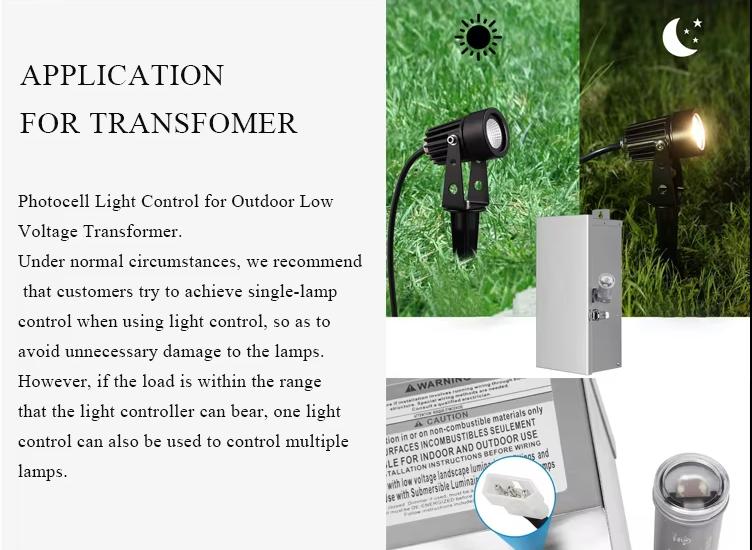
Installing a 120V light sensor switch on a 277V System
This setup causes instant failure. The overvoltage burns internal components. As a result, the photocell stops working.
Solution: Make sure the photocell’s voltage rating matches the fixture’s power supply. This simple check prevents damage before installation.
Low-Voltage Photocells Receiving Insufficient Power
Photocells made for 12V or 24V systems need the correct input to function. If the power supply is too weak, the unit won’t activate the lights. It might seem defective, but it’s just underpowered.
Solution: To avoid this, use wide-voltage models like the JL-404C. It supports 120V to 277V and fits many systems. If the system voltage still doesn’t match, install a transformer or LED driver to adjust the supply.
Overvoltage or Undervoltage Issues
Fluctuations in the power grid can make voltages inconsistent. Their sudden drops or spikes, thus, disrupt normal photocell function. In the long run, they can damage the device.
Solution: Using photocontrollers with built-in overvoltage and undervoltage protection is a smart fix. These models keep the photocell safe from power instability.
How Environmental Factors Degrade Outdoor Light Sensor Switches?
Photoelectric sensors operate outdoors year-round. Harsh environments can break them down over time. In humid or coastal areas, moisture often seeps inside. This causes short circuits or sensor failure. Lightning strikes can also destroy unprotected units instantly. Besides this, UV exposure and extreme temperatures are also leading factors for photosensor degradation.
Practical Solutions
Use IP65 or IP67-Rated Photocells
Choose models with strong waterproof sealing. IP65 protects against water jets. IP67 withstands full immersion. These ratings prevent internal moisture damage. Here is a table outlining different IP ratings and their offered protection.
| IP Rating | Protection Description |
| IP65 | Complete dust protection and resistance to low-pressure water jets |
| IP66 | Dustproof and protected against high-pressure water jets |
| IP67 | Sealed against dust and safe for short-term submersion in water (up to 1m) |
| IP68 | Fully dustproof and suitable for long-term underwater use (manufacturer-specified depth) |
Install Surge-Protected Models
Look for photocells with built-in 10kA or higher surge protection. This guards against power spikes from lightning or electrical faults.
Inspect Regularly and Clean the Socket
Schedule maintenance every 6 to 12 months. Check the socket for rust, dirt, or loose pins. Clean gently with contact cleaner or a soft brush.
What Are Common Communication Failures in Smart Photocells?
Smart photo controllers are integral to modern outdoor lighting systems. They enable advanced features like remote control, dimming, and data collection. However, communication failures can disrupt these functionalities. Here is a closer look.
Common Scenarios
1. Incorrect Wiring of Data Lines
Incorrect wiring of data lines is a common reason smart photocells fail. In NEMA 7-pin setups, pins 4 and 5 are used for 0–10V dimming. Pins 6 and 7 are for digital communication. If these are miswired, the control system cannot read the photocell. Zhaga 4-pin sockets also rely on precise DALI wiring. One wrong connection can stop communication entirely.
Solution: Ensure that all data lines are connected according to the manufacturer’s specifications. Use a multimeter to test continuity and confirm proper connections.
2. Unregistered or Unrecognized Devices
What if your wiring is correct, but the photocells are still not working? This time, the issue could be with the lighting management software.
Solution: Access the lighting management platform to verify that the photocell is recognized and properly registered. Assign unique identifiers as needed and ensure the device is active within the system.
Note: Software issues can also block communication. Wrong network settings or outdated firmware can stop data flow. To fix this, update both the photocell and the system software. Always use the latest firmware to avoid compatibility problems.
How to Avoid Common Light Control Photocell Failures?
Proper installation is the first step toward long-term photocell performance. A few simple checks can prevent the most common failures. Here’s what to keep in mind:
- Always match the photocell’s voltage rating with the power supply.
- Protect wiring from moisture to prevent corrosion and short circuits.
- Mount the sensor away from glass, metal, or other reflective surfaces.
- Look for IP65/IP67 and UL/CE certifications for outdoor use.
- Clean contacts, check function, and replace aging parts regularly.
Final Words
Photocell failures are often avoidable with the right installation and preventive steps. Long-term performance depends on smart choices from the start. For reliable, weatherproof, and certified photocells, Chi-Swear is a trusted name among professionals.


