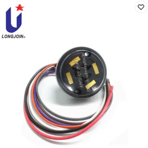
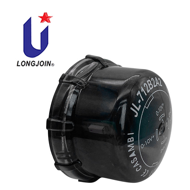
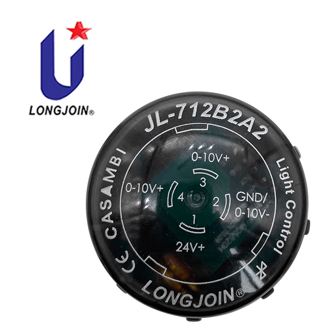
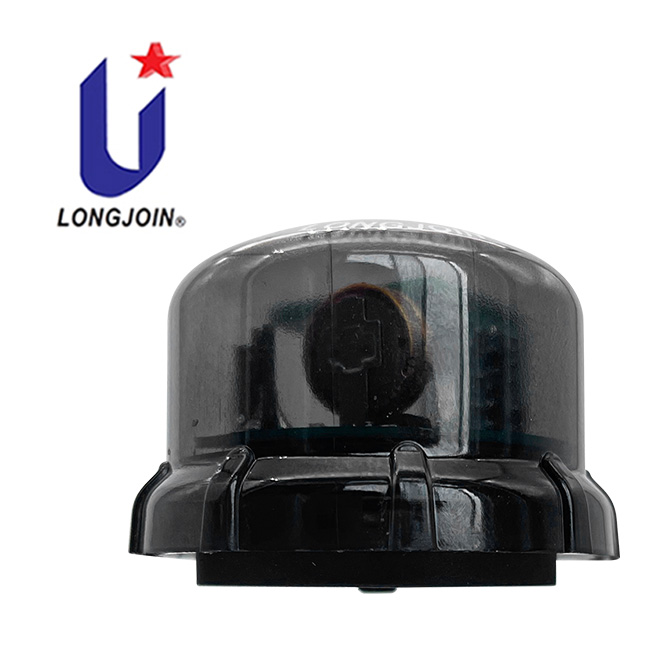

Corriente de alimentación confirmada: 35 mA a 12 VCC o 25 mA a 24 VCC. Estos valores sustituyen las cifras contradictorias de consumo indicadas en tablas de parámetros anteriores. Confirme la capacidad total del driver o de la fuente auxiliar para la instalación seleccionada.
La descripción del producto indica comunicación de malla Bluetooth Casambi y configuración mediante la aplicación Casambi. Confirme el firmware suministrado, el procedimiento de puesta en servicio y los requisitos de la pasarela para el control remoto; no debe suponerse la compatibilidad con un sistema Bluetooth Mesh genérico.
Este modelo indica regulación de 0-10 V y alimentación de 12-24 VCC. Compruebe la asignación de pines del zócalo, la alimentación auxiliar y la entrada de control del driver LED. La descripción del conector por sí sola no demuestra compatibilidad con DALI o D4i.
Confirme el diagrama vigente de cobertura de detección, la altura de instalación, los ajustes de la aplicación y los requisitos de montaje IP66 para el controlador y el zócalo seleccionados. Solicite los registros de certificación vigentes del modelo para las declaraciones CE, Zhaga y RoHS indicadas antes de especificar el producto.
Guías relacionadas: controladores y componentes Zhaga | controles de iluminación inteligente | preguntas frecuentes sobre selección e instalación

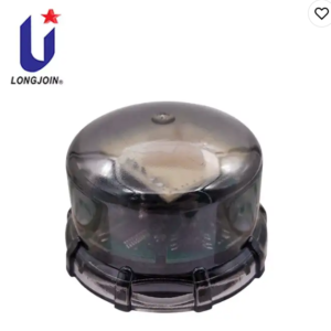
El JL-712B2A2 El producto controlador de luz es un controlador de luz de tipo pestillo inteligente desarrollado en base a Estándar de interfaz Zhaga Book-18Utiliza una combinación de sensores de detección de luz y de detección de microondas, puede generar 0-10 V señales de atenuación y soporte Red de comunicación en malla Bluetooth de CasambiPuede ser controlado por Bluetooth de campo cercano, o ser controlado remotamente por la puerta de enlace Bluetooth.Puede configurar parámetros y escenarios usando el Aplicación Casambi Este controlador de luz es adecuado para escenarios de iluminación como carreteras, céspedes, patios, parques, estacionamientos, fábricas, almacenes, etc.
| Fuente de alimentación | Voltaje: 12-24 VCC Corriente: 12 V/35 mA; 24 V/25 mA |
|---|---|
| Disipación de potencia | Consulte la especificación de corriente de alimentación confirmada al inicio de esta página. |
| Atenuación | 0-10 V |
| Sensores | Sensibilidad a la luz + microondas |
| Rango espectral | 800~1100 nm |
| Frecuencia de microondas | 5,8 GHz |
| Altura máxima de suspensión | 15 metros |
| Radio de inducción | ≥10 metros |
| Hora de inicio | <200 ms |
| Sensibilidad | 80% predeterminado, ajuste a través de la aplicación |
| Escena | Se pueden crear y editar escenas personalizadas a través de la aplicación. |
| vibración mecánica | IEC60068-2-6 |
| Nivel de inflamabilidad | UL94-V0 |
| Temperatura de funcionamiento | -40 ℃ ~ 70 ℃ |
| Temperatura de almacenamiento | -40 ℃ ~ 85 ℃ |
| Humedad de funcionamiento | 5% RH~99% RH |
| Nivel de IP | IP66 |
| Certificaciones | CE, ZHAGA, ROHS as printed in datasheet 2406V1 — manufacturer declaration, no certificate number is given in this datasheet. ZHAGA here refers to the Book-18 interface; it is not a Zhaga-D4i or DALI-2 certification of this model. Ask us for the current certificate scope for your order. |
Datasheet 2406V1 prints both the supply current (35 mA at 12 VDC, 25 mA at 24 VDC) and power-dissipation figures of <0.385 W (12 V) and <0.55 W (24 V). Use the confirmed supply current above as the selection basis. The power-dissipation figures are a datasheet statement, not a measured consumption value, and this page does not repeat them as a selection figure.
| Alfiler | Definición | Función |
|---|---|---|
| 1 | 12–24 VCC | Entrada de potencia |
| 2 | GND / DIM− | Entrada de potencia |
| 3 | DIM+ (0–10 V+) | Salida de señal |
| 4 | DIM+ (0–10 V+) | Salida de señal |
Pins 3 and 4 both output the dimming positive simultaneously. When wiring the socket, either one can be connected to the driver, or both can be connected at the same time. Any unused pin should be insulated. The mating socket determines the conductor colours: in the 700 series socket arrangement shown in the wiring diagram below, brown carries 12–24 VDC, grey carries GND/DIM−, and black or blue carries 0–10 V+.
| Modelo | Feature (as listed in datasheet 2406V1) |
|---|---|
| JL-700 | Normal |
| JL-700W | Self plugging (no-wire connection) |
| JL-700S | Short threaded |
| JL-700T | Probe |
| JL-710 | AC power |
The socket is a separate item and is not supplied with the controller. The controller and the socket are separate scopes of supply: this page covers the controller only. JL-700S and JL-700T have no dedicated page on this site at present — ask us for their drawings and lead time.
| Artículo | What it means for your order |
|---|---|
| Controller | JL-712B2A2 with the firmware and Casambi network configuration agreed for the project. |
| Socket | Ordered separately from the recommended list above; the socket’s pin arrangement must match pins 1–4. |
| Driver | 0–10 V control input plus an auxiliary 12–24 VDC output, or a separate auxiliary supply. If the driver’s auxiliary negative is separate from its dimming negative, the two must be shorted and connected to pin 2. |
| Driver minimum output | The controller cannot cut the driver’s AC supply. Choose a driver whose output current falls close to 0 mA at minimum dimming, otherwise the luminaire may not switch off completely. |
| Gateway | Near-field Bluetooth control works from the Casambi app. Remote control and site-wide scenes need a Casambi-compatible gateway; confirm the model for your project. |
Datasheet download: JL-712B2A2 English datasheet 2406V1 (PDF) — manufacturer original, 9 pages, including dimensions, pin assignment and installation precautions.


Nota: Se puede seleccionar la línea negra o la azul, y también se pueden conectar en paralelo al mismo tiempo.
La interfaz del producto en sí tiene un diseño infalible, la instalación solo necesita apretar el controlador directamente a la base giratoria, como se muestra en la Figura en el sentido de las agujas del reloj después de la inserción.

Condensed from datasheet 2406V1, pages 8–9. These are the conditions that most often decide whether the product works in a given luminaire.
Detection coverage: datasheet 2406V1 gives a maximum mounting height of 15 m and an induction radius of ≥10 m. The coverage chart plotted for 15 m mounting is not circular — the plotted radius is narrowest on the 60°–120° side and widest around 180°–210°. Plan the mounting position against the chart, not against a single radius figure.