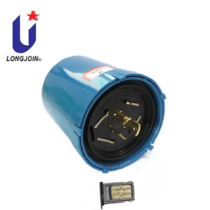
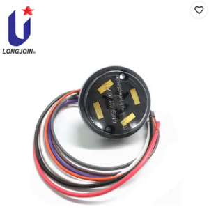
4 Pin Prongs-701A
| Default | Definition |
| 1 | 24VDC |
| 2 | DALI (or DALI based protocol) – /common ground |
| 3 | DALI (or DALI based protocol) + |
| 4 | Port 4 (Black): General I/O |
| Model | JL-700W |
| Voltage | 12-24VDC, 1.5A |
| Feature | Hot pluggable capable |
| Rating protection | Meets 10kV common mode surge test |
| Protective degree | Rated impulse voltage: 0.8kV |
| Range of temperature | -40 to 70°C |
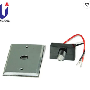
Assemblies

Suggested wires
20~22AWG,lead ends tinned

Connect Diagram
Your Choose Best Connect Diagram, in order to saving more cost , eg, time, strict select supplier quality etc.

| *Scheme 1 for use 700 receptacle | *Scheme 2 for use 710 receptacle |
| When the drive does not have a standard auxiliary power output, additional power supply is required | When using the 710 series socket, the 710 socket has built-in Switching change AC-DC |
Installation Schematic Diagram
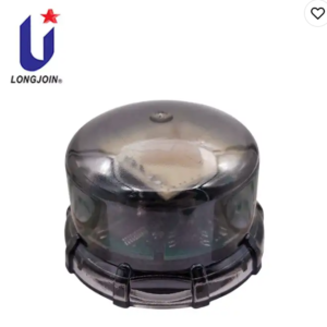
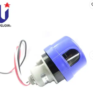
Clockwise twist lock for matching lock its receptacle

Photosensitive or microwave induction mode, and according your customized require design dual compatible mode