Outline
- Introduction
- What Makes the Light Sensor Switch And Contactor Combination So Effective in Modern Outdoor Lighting?
- How Does a Photocontrol Receptacle Actually Work with a Contactor?
- Why Is Using a Photocell Switch With a Contactor Setup Better Than Using a Photosensor Alone?
- Which Long-Join Photosensor Models Are Best Suited for Contactor-Based Systems?
- How Can You Future-Proof Outdoor Lighting with Rugged and Smart Photocells?
- Smart Integration Capabilities
- Final Words
Outdoor lighting needs to be efficient and reliable. But how do you control large lighting systems without constant manual work? The answer is often simpler than people think — a photosensor paired with a contactor. This setup:
- Automates switching
- Handles heavy loads; and
- Keeps components safe from wear
So, regardless of your lighting needs, understanding how these two devices work together can make your system more efficient and durable.
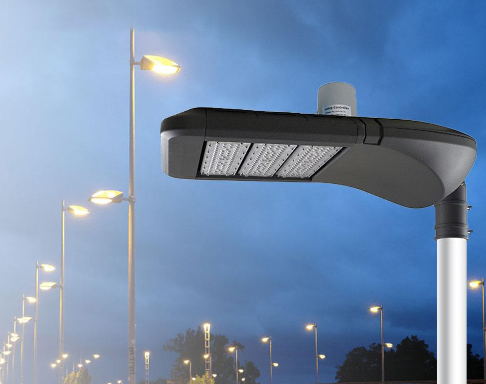
What Makes the Light Sensor Switch And Contactor Combination So Effective in Modern Outdoor Lighting?
The ongoing trend of smart cities lighting demands more than manual control. There is a visible surge in the use of automatic lighting to cut energy use and maintenance.
Lighting controllers switch lights based on daylight. This prevents unnecessary operation and lowers electricity costs. Such systems also boost safety.
How Street Light Controllers and Contactors Complement Each Other
- Photocells detect ambient light using CdS cells and phototransistors. Then, they send a low-voltage signal when light drops below a set threshold.
- Contactors handle the heavy workload. The low-current signal from the photocell energizes the contactor coil, which safely switches high-current lighting circuits.
- This split of duties protects each device: the photocell avoids arc damage, while the contactor avoids wear from operating in low-light conditions.
How Does a Photocontrol Receptacle Actually Work with a Contactor?
Outdoor lighting needs to switch itself based on daylight. A dusk-to-dawn photocell and a contactor make that possible in a smart, efficient way.
Step-by-Step Operation
● Ambient light detection
The street light sensor senses ambient brightness. It trips ‘on’ when light falls below the dusk threshold. It trips off when dawn brightness returns.
● Low-current signal output
The dusk-to-dawn switch uses its internal live (L) and neutral (N) to power its sensing circuit. It sends a small switch output (Lo) to the contactor coil.
● Contactor activation
That low-current signal energizes the contactor’s coil. The energized coil pulls its contacts closed. This safely connects high-current power to the lights.
● Power-off sequence
At dawn, the photoelectric sensor output stops. The contactor coil de-energizes. The contacts open. Lights shut off—automatically.
Simplified Wiring Explanation
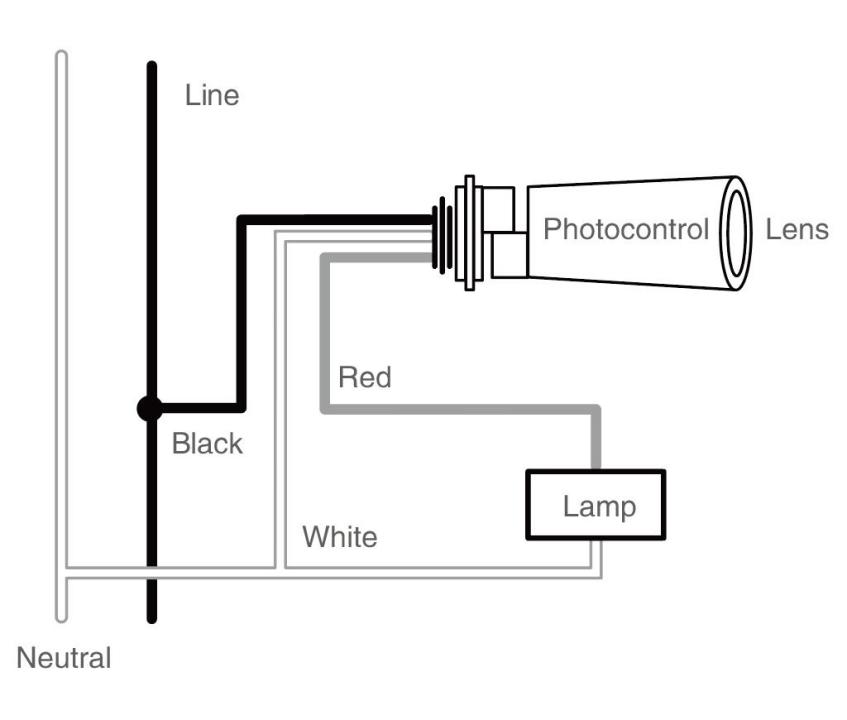
Here’s how the wiring flows:
1. Mains power → circuit breaker → contactor → lighting loads
2. Photocell wired to:
- Live (L1) for its own circuit
- Neutral (N) to complete its sensor circuit
- Load output (Lo) connected to contactor coil (A1)
3. When Lo energizes the coil (with N completing the coil circuit), the contactor closes.
For large installations—like industrial or multi-lamp arrays—you wire the same. But you choose a higher-capacity three-phase contactor rated for your total load. Below is a table showing typical wiring specifications for a photocell contactor system.
| Component | Standard Wire Gauge | Common Voltage Rating | Insulation Type | Max Distance to Contactor |
| Photocell signal wire | 18 AWG | 300V | PVC / XLPE | ≤ 30 m |
| Contactor coil wire | 16 AWG | 600V | PVC / XLPE | ≤ 50 m |
| Load side wiring | 10–12 AWG | 600V | XLPE | ≤ 100 m |
Why Is Using a Photocell Switch With a Contactor Setup Better Than Using a Photosensor Alone?
Using a photocell by itself might seem simple and cheap—but it has limits. Add a contactor to unlock serious performance and reliability gains.
Energy Savings
A photosensor automatically activates lights. That saves energy and avoids wasted electricity. It’s smarter than a timer and works across seasonal daylight shifts.
Handling High Electrical Loads Safely
Outdoor light sensor switches are lightweight switches—not built for high-current loads. Contactors, in contrast, are designed to handle heavy currents. They use arc suppression and durable materials to switch large lighting circuits safely.
Here is a table comparing the load handling capacity of a single photocell and a sensor attached to a contactor.
| Setup Type | Max Current Handling | Typical Applications | Photocell Lifespan Impact |
| Photocell alone | 5–15A | Small circuits, single lamp | Shorter due to high load |
| Photocell + contactor | 30–200A+ | Large lighting networks | Longer due to low coil load |
Extended Photocell Lifespan
Letting a contactor take the hit protects the photocell from arcing wear and electrical stress. That extends the photocell’s life.
Controlling Multiple Circuits
A single contactor can manage several lighting zones—streets, plazas, billboards—with one control signal. That simplifies wiring and centralizes control.
Which Long-Join Photosensor Models Are Best Suited for Contactor-Based Systems?
When you need rugged automation for large outdoor lighting, Long-Join delivers. Their photocells are UL-listed and built for heavy-duty applications. Their designs focus on reliability, compliance, and adaptability—perfect for municipal and industrial needs. Here are the details of some recommended models.
JL-202 Series
- Designed with a thermal bimetallic mechanism and temperature compensation for stable dusk-to-dawn switching. Includes a 30–120 s time delay to avoid false triggering during lightning or passing headlights.
- Twist-lock terminals meet ANSI C136.10-1996.
- The unit is UL-listed for U.S. and Canadian markets.
- Rated for 110–120 VAC, supporting up to 1800 W tungsten or 1000 VA ballast loads.
- Operates in –40 °C to +70 °C range.
JL-207 Series
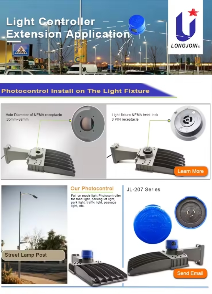
- Features a microprocessor-based design with options for CdS photocell, IR-filtered phototransistor, or unfiltered phototransistor sensors.
- Includes built-in MOV surge protection and a fast 0–20s turn-on delay, plus 5–20s turn-off delay to prevent misoperations.
- It carries ANSI C136.10-2017 twist-lock specs and UL773 listing.
- Rated voltage spans 110–277 VAC (applicable range 105–305 VAC), with a load capacity of 1000 W tungsten or 1800 VA ballast.
- Power draw is just 1.5 VA. On/off threshold: ~6 Lx on, ~50 Lx off.
JL-243 Series

Focused on advanced control needs, these models include “fail-on” mode and midnight dimming capabilities—ideal for applications requiring fallback lighting or adaptive dimming control.
Further, here is a table comparing the features of these products.
| Feature | JL-202 Series | JL-207 Series | JL-243 Series & Custom |
| Voltage Compatibility | 110–277 VAC variants, ±10 % | 110–277 VAC, up to 305 VAC | Likely similar to JL-207 |
| Delay Control | 30–120 s time delay, temperature compensated | 0–20 s turn-on, 5–20 s turn-off | Midnight dimming delay |
| Surge Protection | Available MOV options (110 J / 235 J / 460 J) | Built-in MOV (customizable joule rating) | Not specified, customizable |
| IP / Housing | Twist-lock, durable polycarbonate/plastic housing | Twist-lock, high-impact materials, UL listed | NEMA-style, robust for fail-on |
| Load Capacity | 1800 W tungsten / 1000 VA ballast | 1000 W tungsten / 1800 VA ballast | Similar or higher |
| Certifications | ANSI C136.10-1996; UL (US & Canada) | ANSI C136.10-2017; UL773 (US & Canada) | UL and custom options |
How Can You Future-Proof Outdoor Lighting with Rugged and Smart Photocells?
Modern lighting must handle extreme conditions. It must also support future-ready connectivity. Rugged and smart photocells meet both needs.
Ruggedization for Harsh Climates
● IP68 Waterproofing
Select photocells with an IP68 rating. This shield is against dust and water immersion.
● UV-Resistant Housing Materials
Long-term durability requires UV stability. These materials stop fogging and cracking, which can reduce sensor performance over time.
● Salt-Fog Resistance for Coastal Installations
Coastal environments need corrosion-proof designs. Reinforced housings with stainless steel or treated finishes block damage from salt spray and high humidity.
Smart Integration Capabilities
● NB-IoT / LoRa Communication
Many smart photocells use communication protocols like NB-IoT or LoRa. This allows lighting systems to send data-like status and fault alerts.
● Fault Feedback for Maintenance Teams
Remote communication lets sensors report failures in real time. Teams can see bulb burnouts or misfires immediately, leading to speedy repairs.
● Memory Functions for State Recovery
If connectivity fails, non-volatile memory such as EEPROM or Flash stores the last operating state. Once the link returns, the system resumes correctly without a manual reset.
Final Words
Smart photocells improve efficiency and system control in outdoor lighting. For lasting performance, choose rugged designs with smart integration features. Chi-Swear supplies reliable Long-Join smart photocells trusted by professionals worldwide.
External Links
- https://en.wikipedia.org/wiki/Photoresistor
- https://www.nema.org/standards/technical/ansi-c136-series-standards-for-roadway-and-area-lighting-equipment
- https://www.ul.com/resources/apps/standards-catalog
- http://www.julixing.com.cn/en/new/new-58-907.html
- https://en.wikipedia.org/wiki/Narrowband_IoT
- https://en.wikipedia.org/wiki/LoRa


