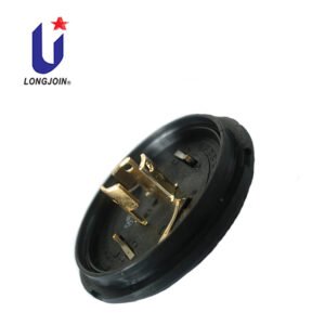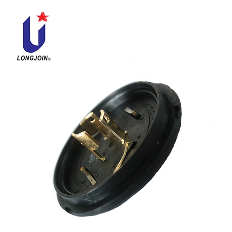
Respuesta rápida. Qualifying a NEMA photocontrol base supplier means answering seven questions with documents rather than assurances: does the interface match mechanically; do the contact materials and electrical evidence support the load; is the certification scope current and applicable; can the supplier exchange engineering data and control revisions; are manufacturing quality controls in place; does a sample survive your own validation; and can the supplier sustain volume with change notification. A supplier that cannot evidence the first two is not ready for approval at any price, because those are the two the field will find out about.

Why Is Supplier Qualification Important for Smart Lighting Controller OEMs?
Most lighting-control OEMs do not make the base. They buy it, integrate it into a controller, and ship that controller into a luminaire that a municipality expects to run for a decade. The base is a small fraction of the bill of materials and a large fraction of the field-failure risk, because it is the one component that is repeatedly mated, exposed to weather and electrically loaded.
The commercial exposure is asymmetric. A rejected batch found in incoming inspection costs a delay. The same defect discovered in the field costs replacements, truck rolls, warranty labour, a municipal relationship and, in a public project, reputational damage that outlasts the product. Supplier qualification is the process of moving that discovery as far upstream as possible — ideally to a document review, before any parts are made.
There is a second reason that matters more for smart controllers specifically. A modern controller carries dimming and communication signals alongside power, so the base is no longer only a power connector. It is part of a signal path whose stability affects functionality, not just safety. A resistance drift that would be tolerable on a power contact can be a functional fault on a 0–10 V control line.
Step 1 — Verify NEMA Interface Compatibility
3-Pin vs 5-Pin vs 7-Pin Configurations
Pin count defines function, not just geometry. A 3-pin configuration carries power and switched output. A 5-pin or 7-pin configuration adds control positions for dimming and, in the 7-pin case, additional signal or communication contacts under ANSI C136.41. The interface standard that applies depends on the configuration, and a qualification file built for one configuration should not be reused for another without checking the differences.
Before comparing quotations, establish which configuration your controller actually needs, and confirm that the supplier’s document set covers that exact code. Product families often span several configurations; a datasheet covering the family is not evidence for a single variant.
Mechanical Dimensions and Mating Requirements
Interface compatibility is a dimensional claim, and it should be checked against a drawing rather than a photograph. The critical items are the contact positions, the locking feature geometry, the keying arrangement that prevents incorrect insertion, the overall envelope, and the sealing arrangement. On a gasketed assembly, the seal is part of the interface: a base that seals correctly against one receptacle may not seal against another with different surface finish or flatness.
Mating requirements also include insertion and removal force. Too high and installation becomes inconsistent, which is a real cause of damaged contacts in the field; too low and the assembly may not stay seated under vibration. Neither figure can be assessed from a catalogue.
Power Contacts vs Signal Contacts
One important distinction that buyers often collapse: the base is not a single electrical component. It has power contacts that carry load current and signal contacts that carry control signals, and the two have different ratings, different materials and different failure modes. Long-Join’s documentation for the JL-241J, for example, lists a power interface rating of maximum 480 Vac at 15 A rated loading and a signal circuit rating of 0–30 Vdc at 250 mA, with H62 brass power contacts and phosphor bronze dimming pins.
Applying the power rating to the signal contacts, or testing only the power path, is a common qualification error. Both paths need their own evidence.
Step 2 — Evaluate Contact Materials and Electrical Performance
This step is where the technical depth sits, and it is covered in detail elsewhere in this series: contact resistance and plating quality for the interface mechanism, reliability testing for the test methods, and gold-over-nickel plating for the finish system. What a supplier qualification review needs from those areas is a document set, not a deeper explanation:
- Contact substrate per contact group, with the alloy identified — not just “copper alloy”.
- Especificación de recubrimiento per region, with the underplate stated.
- Resistencia de contacto with the measurement method, test current and sample quantity, ideally before and after conditioning.
- Aumento de temperatura at the rated current, with the mounting arrangement described.
- Mating durability with the cycle count and the mating receptacle identified.
One caution on reading this list: a supplier may hold some of these and not others. The qualification decision is not “does the supplier have everything” but “is every gap recorded and accepted against a defined risk”. An open item that is known and accepted is manageable; an open item that was assumed closed is not.
Step 3 — Review Certification and Compliance Documentation
Four distinct claims are often merged in a supplier’s presentation, and they should be kept apart:
| Claim | What it actually means | What the buyer must do |
|---|---|---|
| UL Recognized Component | The component has been evaluated to applicable requirements under conditions of acceptability, for integration into a larger product that will be certified | Confirm current file scope, exact model, ratings and conditions of acceptability |
| UL Listed end product | A complete product is certified for its intended use | Verify it applies to the product you are buying, not the controller you build |
| ANSI C136.10 / C136.41 interface compatibility | The interface conforms to the published mechanical, electrical and marking requirements for the control type | Confirm which edition, and that your configuration is covered |
| RoHS documentation | Restricted substances declaration for the materials supplied | Check the declaration matches the part number and revision |
These are separate because they answer separate questions. Interface conformity does not imply certification; certification does not imply interface conformity to the latest edition; and neither implies that your customer-specific validation has been done. Reconocido por UL vs. Probado para garantizar la fiabilidad covers the distinction in full.
Step 4 — Assess Engineering and CAD Design Support
This is a question that arrives in almost every serious OEM enquiry, and it is worth answering directly rather than in generalities. Buyers ask whether a supplier works in Creo, SolidWorks, Siemens NX or another platform, and whether STEP/STP files, 2D dimensional drawings and design revisions are available.
The honest answer is that the CAD platform is not the qualification criterion. What matters is whether the supplier can deliver accurate, current engineering data in a format your team can use, and whether it can manage revisions without ambiguity. A supplier using your preferred software but shipping stale drawings is a worse partner than one using a different platform that reliably exports clean STEP files and controls revisions.
So the questions that actually discriminate are:
- Can you supply a STEP (AP214 or AP242) file of the exact configuration, dimensioned to match the 2D drawing?
- Is the 3D model a true representation of the production part, including contact positions and the locking feature?
- How are drawing revisions identified, and how will I be notified when geometry or material changes?
- Can you review a change request and return a manufacturing feasibility assessment?
- Which 2D drawing format do you issue, and does it carry tolerances and a revision block?
A note on claims: this article does not state which CAD platform Long-Join uses for the JL-241J, because that has not been formally confirmed as a published capability. What can be stated is the requirement — a supplier should be able to say plainly which formats it can deliver, and support that statement with a sample file before you commit to a programme.
Step 5 — Review Manufacturing Quality Control
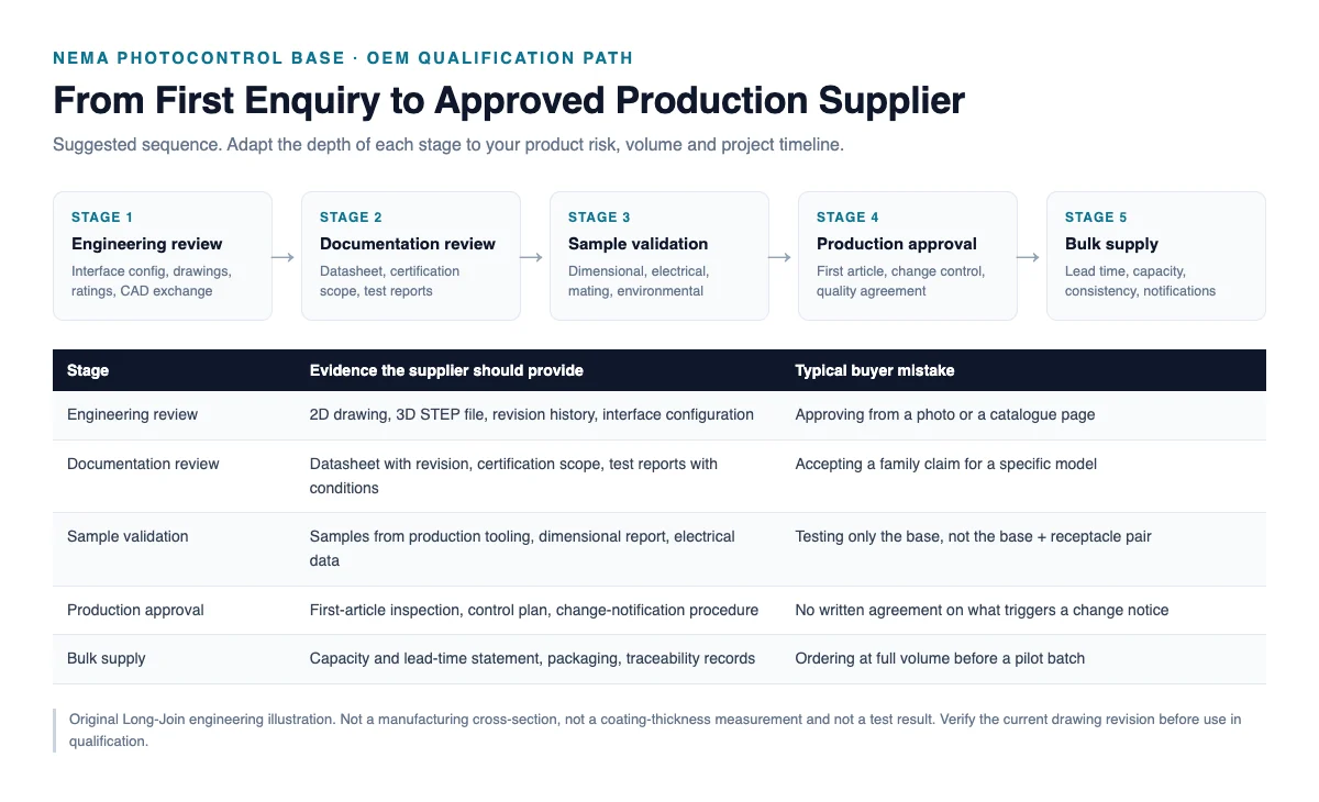
Quality control is a process claim, so ask for the process documents rather than a certificate. The six elements below are the minimum an OEM normally expects, and each should be evidenced by a procedure, a record or a sample report:
| Elemento | What it should cover | Evidence to request |
|---|---|---|
| Incoming material inspection | Verification of resin grade, contact alloy and plating input | Inspection plan and a sample record |
| In-process inspection | Moulding parameters, insert placement, assembly checks | Control plan with check frequency |
| Final inspection | Dimensional, visual and electrical checks on finished parts | Sampling plan and acceptance criteria |
| Material traceability | Link between a shipped lot and its material batches | Lot marking scheme and traceability record |
| Nonconformance control | Segregation, disposition and corrective action | NCR procedure and a closed example |
| Change management | Notification before material, process or tooling changes | Written change-notification procedure |
Two of these are more valuable than the rest in practice. Change management is the one that prevents silent substitution — a material or plating change that nobody told you about is the classic cause of a product that passed qualification and fails a year later. Material traceability is what allows a field problem to be bounded to a lot instead of a shipment year. If a supplier cannot describe either process in specific terms, treat the whole quality section as unverified rather than assume a standard system exists.
Step 6 — Perform Sample and Engineering Validation
Samples are where documents meet reality, and the validation should be structured rather than exploratory:
- Drawing review — compare the supplied drawing against your interface requirements before parts arrive.
- Dimensional check — critical dimensions against the drawing, with the gauge and method defined.
- Electrical measurement — contact resistance at both power and signal positions, using a four-wire method.
- Mating test — with the receptacle you will actually use, measuring insertion and removal force and checking seating.
- Environmental requirement — the exposures your market requires; salt spray or damp heat as applicable.
- Evaluation approval — a written record of what passed, what was waived and on what basis.
Samples should come from production tooling, not from a pilot build, and the report should say so. A sample made on a different tool can differ in dimensions and in process control from what you will receive in volume — and the difference usually appears in exactly the areas that are hardest to inspect.
Step 7 — Evaluate Bulk Supply Capability
Commercial capability is the last step and the one most often taken on trust. Ask for statements that can be checked: production capacity relative to your annual volume, standard lead time with the basis stated, minimum order quantity, tooling ownership and maintenance arrangements, and the process for capacity constraints. A supplier who cannot state a lead-time basis has not given you a lead time.
Three questions deserve specific attention. First, change notification: what triggers a notice, how much notice, and to whom. Second, long-term supply: what happens if a material or a sub-supplier becomes unavailable, and is there a last-time-buy arrangement. Third, consistency: what evidence exists that lot-to-lot variation is controlled, which is a process question, not a capacity question.
No capacity, yield, lead-time or minimum-order figure is quoted for the JL-241J in this article. Those are commercial commitments that must come from the supplier for your specific order, in writing.
NEMA Photocontrol Base Supplier Scorecard
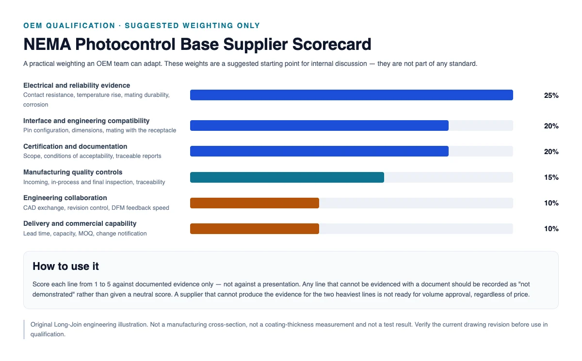
The weighting below is a suggested starting point for an internal discussion. It is not an international standard, and it should be adjusted to the risk profile of the project — a coastal municipal programme and a sheltered industrial retrofit do not weight corrosion evidence the same way.
| Dimensión | Suggested weight | What evidence scores it |
|---|---|---|
| Interface and engineering compatibility | 20% | Drawing match, dimensions, mating with the actual receptacle |
| Electrical and reliability evidence | 25% | Contact resistance, temperature rise, mating durability, corrosion — with method and values |
| Certification and documentation | 20% | Current file scope, conditions of acceptability, traceable reports |
| Manufacturing quality controls | 15% | Inspection plan, traceability, nonconformance and change control procedures |
| Engineering collaboration | 10% | CAD exchange, revision control, responsiveness to design queries |
| Delivery and commercial capability | 10% | Lead-time basis, capacity, MOQ, notification commitments |
Two rules make a scorecard useful rather than decorative. Score only against documented evidence — a presentation is not evidence. And record any line that cannot be evidenced as “not demonstrated” rather than awarding a neutral middle score, because the middle score quietly converts an unknown into a pass.
JL-241J as a Practical OEM Evaluation Example
Applied to a real product, the process looks like this. The JL-241J NEMA 7-pin base is documented with PBT base material, a power interface rating of maximum 480 Vac at 50/60 Hz and 15 A rated loading, a signal circuit rating of 0–30 Vdc at 250 mA, an operating range of −40 °C to +70 °C, and a sealing arrangement that must match the approved assembly drawing. Material groups are differentiated: H62 brass for power contacts, phosphor bronze for the four dimming pins, with gold and tin finishes over nickel under-plating.
What that documentation supports is an engineering comparison — configuration, ratings, materials, interface. What it does not do is replace the qualification steps above. Certification status must be verified against the current record; test evidence for your specific acceptance criteria must be requested; CAD exchange capability and manufacturing quality procedures must be confirmed directly; and commercial terms must be agreed in writing.
Product information: Base de fotocontrol JL-241J NEMA. Deeper technical background is in the pillar guide, Cómo evaluar la fiabilidad de una base de fotocontrol NEMA antes de realizar una compra al por mayor..
Preguntas frecuentes
What should OEM buyers verify before selecting a NEMA base supplier?
Seven things, each with a document behind it: interface dimensions against your drawing; contact materials and electrical evidence for both power and signal paths; certification scope and conditions of acceptability for the exact model; CAD exchange and revision control capability; manufacturing quality procedures; a sample validation result on production-tooled parts; and commercial terms including lead time, capacity and change notification.
Is UL Recognition enough for supplier qualification?
No. Component recognition confirms the component has been evaluated to applicable requirements under conditions of acceptability. It does not confirm that your durability, temperature-rise or corrosion criteria have been met, nor that manufacturing quality controls are in place, nor that the supplier can sustain volume. It is one input among several, and it needs to be current for the model you are buying.
Can suppliers provide STEP files for controller integration?
Suppliers of this class of component commonly can, but availability and model fidelity vary, so ask for a sample before committing. The useful request is a STEP file of the exact configuration that matches the 2D drawing and the production part, together with a statement of which AP version it is exported in and how revisions are identified.
Does CAD software choice affect supplier qualification?
Not directly. The platform is a working preference; the qualification criteria are accuracy, format compatibility and revision control. A supplier on a different CAD platform that delivers reliable STEP files and disciplined revisions is a better partner than one on your platform that delivers stale drawings. Judge the deliverables, not the software name.
Should the base and receptacle be tested together?
Yes, at least once in the programme. The contact interface is a pair: plating, contact geometry, tolerances and contact force are properties of the mated system. Testing a base alone against an unspecified receptacle produces a result that may not transfer to your assembly, and it will not reveal finish incompatibility between the two suppliers’ parts.
What documents are needed before volume purchasing?
Approved drawing with revision; material and finish specification; certification scope with conditions of acceptability; test reports for the requirements in your specification, each with method, conditions, sample quantity, acceptance criteria and measured values; first-article inspection report; quality agreement or control plan; and written commercial terms covering lead time, capacity, MOQ and change notification.
Conclusiones clave
Supplier qualification is a document exercise before it is a commercial one. Interface compatibility, electrical and reliability evidence, certification scope, engineering data exchange, manufacturing controls, sample validation and bulk supply capability each require a specific artefact — and any line without one should be recorded as open rather than assumed. The CAD question is about deliverables, not software brands. Certification answers a narrower question than most buyers assume. A weighted scorecard helps only if it is scored strictly against evidence, and the two heaviest dimensions are the two the field will test first.
Request a JL-241J OEM supplier qualification package.
Send us your programme requirements and we will respond with the documentation available for your configuration, and a clear statement of which items require further verification.
- Company name and business email
- Required configuration and controller application
- CAD and drawing requirements (formats, 2D/3D)
- Certification and test requirements
- Expected annual volume and project timeline
Referencias y fuentes técnicas
- Cómo evaluar la fiabilidad de una base de fotocontrol NEMA antes de realizar una compra al por mayor. — pillar guide covering the overall evaluation sequence.
- ¿Por qué son importantes la resistencia de contacto y la calidad del recubrimiento en las bases de fotocontrol NEMA? — contact interface and materials.
- What Tests Should a NEMA Photocontrol Base Pass? — test methods and report review.
- Reconocido por UL vs. Probado para garantizar la fiabilidad — certification scope and verification.
- ¿Cómo mejora el recubrimiento de oro sobre níquel la fiabilidad del contacto base del fotocontrol? — finish system engineering.
- ANSI C136.41-2025 — Requisitos de interfaz para controles y luminarias de tipo bloqueo externo.
- UL Solutions — Components certification — scope of component certification programmes.