Outline
- Introduction
- What Is the JL-215C Photocontroller’s Power-On Flicker Phenomenon?
- Why Does the JL-215C Photocell Switch Flicker During Power-On?
- How Does JL-215C Excel In This Phenomenon?
- What Professional Recommendations Can Improve System Design?
- Why Choose the LongJoin’s JL-215C?
- How Can Understanding This Issue Help Ensure Project Success?
- Final Words
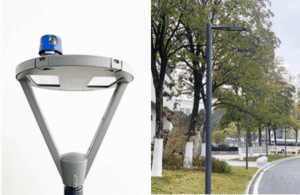
Smart cities rely on an intelligent street lighting system. This helps ensure energy efficiency and safety. But what happens when the lights flicker at power-on? Many customers have noticed a brief flash with the JL-215C light sensor before it enters normal operation. This article explores:
- Why does that flicker happen
- What it means for your project, and
- How to minimize its impact.
Our engineering team breaks it down in simple terms and offers practical solutions for stable, professional lighting control.

What Is the JL-215C Photocontroller’s Power-On Flicker Phenomenon?
When power is applied to the JL-215C lighting control, the load (e.g., street lamp) often flashes once very briefly before the photocell’s sensor and relay stabilize and begin normal light/dark control. That flash comes from the relay contacts closing momentarily before the control circuit reaches its running state.
The startup flicker matters because:
- It can look like a defect. This may trigger unnecessary warranty claims or frustrate customers.
- In systems with motion sensors, dimmers, or LED drivers, even a brief flicker can stress components. It can also create a noticeable light “pop.”
- Frequent power interruptions make the problem worse. More flickers hurt visual comfort, reduce perceived reliability, and may affect project acceptance.
Why Does the JL-215C Photocell Switch Flicker During Power-On?

The JL-215C is designed in Fail-On mode, meaning that if the control circuit is not yet active or fails, the relay contacts default to closed so that the light stays on.
At power-up, before the photocontrol receptacle’s sensing and control circuitry has reached a stable operating condition (photo-sensor, internal voltage regulators, relay driver), the relay closes briefly. That contact closure causes a momentary light flash.
The safety purpose: ensuring public safety and continuous illumination in case the photocontrol fails or in case of sensor or circuit delay. In Fail-On, lights do not remain dark if something is wrong.
How Does the JL-215C Compare with JL-205 in Flicker Behavior?
From product specifications:
- Both JL-215C and JL-205 support Fail-On mode.
- JL-205 includes a time-delay of 3-20 seconds feature, which helps to avoid misoperations from brief light pulses (lightning, spotlights) at night.
- The response circuitry in JL-205 appears to stabilize faster, closing or opening the relay sooner, thus reducing visible flicker duration. (Because its delay function helps defer activation or deactivation, controlling when contact occurs after ambient light crosses the threshold.)
Why JL-205’s flicker is less perceptible
Shorter relay actuation delay or quicker sensor threshold crossing means less time with the relay closed before the control logic takes over.
For many LED lamps, the brief closure is too short or weak to drive illumination above the human visible threshold. Time delay (3-20s) in JL-205 smooths transitions, reducing perceptible flicker. Here is a table comparing the two products.
| Feature | JL-215C | JL-205 |
| Fail-Safe Mode | Fail-On (default closed) | Fail-On (default closed) |
| Typical Relay Stabilization | ~200–300 ms | <100 ms |
| Visible Flicker | More noticeable | Rarely visible |
| Time Delay Range | 3–20 seconds | 3–20 seconds |
| Best Use Case | Streetlights, parking areas | Smart poles, architectural lighting |
How Does Power Supply Continuity Affect Flicker Frequency?
With a continuous, stable supply of power, the flicker happens only once. This is at the initial power-on, when the circuit transitions from no power to powered. After that, the photocell stays in its control loop.
With frequent power interruptions:
- Every restoration of power triggers the same startup sequence: relay default closure, then sensor stabilization. Each cycle causes a flicker.
- Thus, if power is cut and restored repeatedly (e.g., for maintenance, manual switching, grid fluctuations), flicker events multiply, possibly causing annoyance or wear on lamp drivers.
Here is a table showing the recommended maximum power cycling frequency for various applications.
| Application Scenario | Recommended Power Cycling | Reason |
| Smart Street Lighting (Urban) | ≤ 1 cycle per day | Prevents frequent visible flickers and extends driver lifespan |
| Highway Lighting | ≤ 1 cycle per week | Maintenance shutdowns only |
| Smart Poles with IoT Devices | Continuous power recommended | Avoids multiple device reboots and data loss |
| Test Benches / Commissioning | Unlimited (for testing) | Controlled environment, not user-facing |
How Does JL-215C Excel In This Phenomenon?

The rated VAC for JL-215C is 110-277 VAC. Further, its applicable range is around ~305 VAC. It has a preset time delay of 3-20 seconds to avoid misoperation from transient light (e.g., headlights, lightning). It supports Fail-On mode (fail-safe closed) so that the relay defaults to closed until the control circuitry becomes stable.
Flicker Is Not a Defect but a Design Feature
The startup flicker is a built-in behavior linked to the Fail-On mode and the time delay. It is not a manufacturing fault.
The relay’s momentary contact closure at power-on is intended to ensure lights are on until the photocell decides based on ambient light. It preserves safety and compliance.
How System Power Cycling Impacts User Experience
- If power remains continuously supplied, the flicker happens only once—at initial power-on.
- If power is frequently interrupted (e.g., manual switch-offs, maintenance, unstable grid, or control boxes), every restoration triggers the same flicker.
- Multiple flickers can degrade perceived reliability, especially with LED lamps sensitive to quick transitions or in user-visible installations.
What Professional Recommendations Can Improve System Design?
Firstly, notify customers that the brief flicker at startup is part of the Fail-On (fail-safe closed) mode, not a defect. Also include this behavior in spec sheets and user manuals, so integrators expect it.
Provide guidance on what kinds of lamps/load types make the flicker more visible (e.g., sensitive LEDs vs high-inrush ballasts), so customers can anticipate visibility.
How Should System Design Be Done to Minimize Flicker Events?
Design systems with continuous power when possible
- Avoid unnecessary power interruptions (e.g., due to manual switching, auxiliary control boxes, or grid instability), because each power restoration triggers a startup flicker.
- Use surge protection (JL-215C includes a built-in MOV surge arrester) to reduce spurious operations, but this alone won’t prevent flicker at power-on.
Optimize the electrical and mechanical setup
Ensure voltage supply remains within rated range (110-277VAC, applicable up to ~305VAC) to avoid added delays or instability.
Use proper mounting so that the photocell’s sensor is unobstructed and clean (reduces additional delay in sensing).
What Custom Solutions Can Be Offered for Special Applications?
For installations where flicker must be imperceptible or absolutely controlled:
- Offer versions or configurations with faster control circuit stabilization. Possibly reduce time delay or adjust relay actuation speed.
- Provide adjustable delay settings (if feasible) so projects in darker or more sensitive environments can set longer delays, suppressing visible flicker.
- Offer photocell models (or firmware/hardware variants) with dimming or soft-start integration so that startup does not immediately switch to full power (which reduces visible impact).
- In smart city / IoT integration, support communication protocols or additional control logic so that system controllers can manage startup sequences (e.g., pre-charge, staged startup) where needed.
Why Choose the LongJoin’s JL-215C?
The JL-215C light sensor switch brings strong features built for demanding smart lighting deployments.
Voltage Compatibility & Surge Resistance
It operates over a wide voltage range. It includes a built-in surge arrester (MOV) for protection against voltage spikes.
Weather Resistance & IP Ratings
The weather sealing options include IP65 and IP67. This ensures protection from harsh outdoor conditions. Talking about extreme temperatures, it can withstand between −40°C and +70°C.
Smart City Integration & Standards Compliance
The physical design uses ANSI C136.10 twist-lock terminals. This complies with UL773 standards, making it easy to integrate into standard street light fixtures. Built-in delay, i.e, 3-20 seconds, helps avoid false activations from lightning or transient light sources.
Certifications & Quality Assurance
Manufacturing meets international standards in material quality and production control. The JL-215C is certified under CE, UL, and RoHS.
| Certification | What It Covers |
| UL773 | Photocontrol safety standard |
| CE | European compliance |
| ISO9001 | Quality management |
| RoHS | Hazardous substances |
Reliability
Robust surge protection extends component life. Low power draw (≈0.5W) helps reduce energy waste. Weather seals and high IP ratings reduce failures due to moisture and environmental exposure.
How Can Understanding This Issue Help Ensure Project Success?
Recognizing the JL-215C flicker as normal startup behavior saves time. When integrators know in advance, they avoid misdiagnosing it as a defect. That lowers return rates and stops unnecessary support tickets.
Technical awareness among project teams reduces delays. Engineers prevent wasted work by accounting for startup relay closure in control logic, wiring, and customer expectations. Projects with LED fixtures especially see fewer surprises when this is factored into the design.
Understanding flicker helps improve visual comfort. In installations visible to people, like streets or parks, knowing when and how flickers happen keeps stakeholder satisfaction high.
If you’re still in doubt, get in touch with us. We provide detailed spec sheets, test reports, or custom configurations. Let’s make sure your smart lighting project meets its reliability, aesthetic, and safety goals.
Final Words
The JL-215C’s flicker is not a fault. It is a normal startup response designed for stable performance. Knowing this helps avoid unnecessary troubleshooting and project delays. For reliable JL-215C smart photocells, work with Chi-Swear. Their supply chain, QC, and technical support ensure smooth integration into your lighting projects.
External Links
- https://en.wikipedia.org/wiki/Varistor
- https://www.nema.org/docs/default-source/standards-document-library/ansi-c136-10-2017-contents-and-scope.pdf?sfvrsn=36d2efb_2
- https://www.nema.org/docs/default-source/standards-document-library/ansi-c136-10-2017-contents-and-scope.pdf?sfvrsn=36d2efb_2
- https://www.iec-equipment.com/new/new-31-969.html
- https://en.wikipedia.org/wiki/CE_marking
- https://www.ul.com/solutions
- https://en.wikipedia.org/wiki/RoHS