概要
- 導入
- What Are the Common Types of Long-Join 光制御 Wiring?
- What Are the International Wire Color Standards Across Different Regions?
- How Does Long-Join 光電センサー Wiring Compare with International Standards?
- How Should Long-Join Photocells Be Wired for Different Socket Types?
- What Are the Best Practices to Avoid Wiring Errors in 照明制御 インストールですか?
- 結びの言葉
Outdoor lighting depends on reliable control. フォトセルスイッチ play a key role in this system. Long-Join wiring ensures stable and accurate switching.
But wiring is not always straightforward. Different regions use different wire color standards. This creates confusion during installation.
A wrong connection can damage the device. It can also cause safety risks. Clear wiring knowledge is essential.
This guide explains Long-Join 光電セル照明センサー wiring. It also compares it with international standards. The goal is simple—help you wire correctly and avoid costly mistakes.

What Are the Common Types of Long-Join 光制御 Wiring?
Confused about which wiring type to use? Choosing the wrong configuration can limit performance. This section breaks it down clearly and practically.
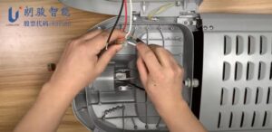
光センサー That Use Wiring-Type Connections
Models like JL-403C, JL-423C, and JL-428C are typical 配線式光電池. They are designed for direct wiring into lighting circuits.
They are widely used in:
- Street lighting and roadway systems
- Wall packs and building exteriors
- Garden, pathway, and landscape lighting
These models operate on 120–277VAC and support basic automatic switching control. They use lead wires instead of plug-in sockets, making them flexible for retrofit and OEM applications.
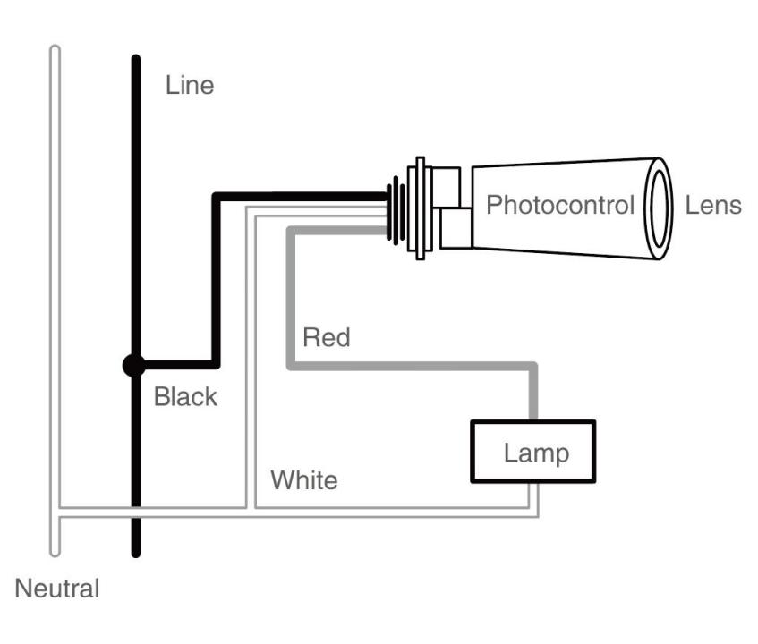
Standard 3-Wire Wiring
The 3-wire setup is simple but critical. Each wire has a fixed role:
- Black → Live (Line input)
- Red → Load (output to lamp)
- White → Neutral (circuit return)
This structure allows the 光センサースイッチ to act as a controlled switch. It powers itself while switching the load safely. Incorrect mapping will stop the system from working properly.
Functional Role of Each Wire in Operation
| 配線色 | 関数 | Electrical Role | Connection Point |
| 黒 | Live (Line) | Supplies input power | Main power source |
| 赤 | 負荷 | Sends switched power to the fixture | Lamp/driver input |
| 白 | 中性 | Completes circuit | Neutral bus |
Signal Wires in Advanced Socket Configurations
Advanced systems require dimming and control signals. This is where extra wires come in.
● 5-pin socket
Grey and Violet wires carry 0~10V調光 signals. Used in energy-saving lighting systems.
● 7-pin socket:
Brown and Purple wires support ダリ communication. Ideal for smart lighting and centralised control.
These signal wires do not carry power. They transmit control signals for brightness and automation.
What Are the International Wire Color Standards Across Different Regions?

These standards vary across countries. Mixing them up can cause wiring faults and safety risks. Here is a clear breakdown for accurate matching.
EU Wire Color Standard
The EU follows IEC harmonized standards. These are widely adopted across Europe.
- Live (L): Brown
- Neutral (N): Blue
- Ground (PE): Yellow-green
This system is consistent and easy to identify. It separates safety grounding clearly from current-carrying conductors.
US Wire Color Standard
The US uses NEC guidelines. These allow more flexibility for live conductors.
- Live (L): Black, Red, and other colors
- Neutral (N): White
- Ground (G): Green or bare copper
Live wires can vary by circuit. This increases complexity during international installations.
Australia and the UK, too, align closely with IEC standards. This makes compatibility easier with European systems. However, Older UK systems used different colors. Modern installations follow this updated scheme for consistency.
How Does Long-Join 光電センサー Wiring Compare with International Standards?
Mixing all wire colors causes most installation errors. Long-Join follows a North American-style scheme. Many regions do not.
Comparison of Wire Color Definitions
| Wire Function | Long-Join Definition | EU (IEC) | US (NEC) | オーストラリア | UK |
| Live (L) | 黒 | 茶色 | Black/Red | 茶色 | 茶色 |
| 負荷 | 赤 | – | – | – | – |
| Neutral (N) | 白 | 青 | 白 | 青 | 青 |
| Ground (G) | – | Yellow-green | Green/Bare | Yellow-green | Yellow-green |
| 5-pin Signal | Gray, Violet | – | – | – | – |
| 7-pin Signal | Brown, Purple | – | – | – | – |
主な違い
The biggest mismatch is in Live and Neutral wires.
- Long-Join uses Black for Live, while EU/UK/AU use Brown
- Long-Join uses White for Neutral, while EU/UK/AU use Blue
- The Red wire (Load) has no direct equivalent in IEC systems
These differences are small in appearance but critical in function.
Risks Come from Incorrect Assumptions
Assuming the color function can lead to failure. Installers may connect wires based on local habits, not product logic.
- The wrong Live/Neutral connection stops the operation
- Miswiring can damage the photocell or the load
- Safety risks increase in outdoor installations
Always follow the wiring diagram. Never rely only on color familiarity.
How Should Long-Join Photocells Be Wired for Different Socket Types?
Not sure which wiring method fits your system? Each socket type serves a different control level. Choosing the right one ensures stable operation and proper functionality.
Wiring a 3-Wire 光制御レセプタクル
This is the most common and simplest setup. It is used for basic dusk-to-dawn control.
- Black → Live (input power)
- Red → Load (to lamp)
- White → Neutral
その 光電セルセンサー acts like a switch. It cuts or supplies power based on light levels. No dimming or communication is involved. This setup is ideal for street lights and floodlights where only ON/OFF control is needed.
Wiring Work in a 5-Pin Socket フォトスイッチセンサー
This setup adds dimming capability. It builds on the standard 3-wire structure.
- Core wires remain the same (Black, Red, White)
- Gray & Violet → 0–10V dimming signals
These extra wires connect to LED drivers. They control brightness levels instead of just switching. This improves energy efficiency and extends fixture life.

7-Pin Socket Photocell 配線
This is designed for advanced systems. It supports smart city lighting control.
- Includes all 5-pin functions
- Brown & Purple → DALI communication lines
DALI enables two communication channels. Lights can be monitored and scheduled remotely. This setup is ideal for intelligent lighting networks and centralized control systems.

Comparison of 3-Wire vs 5-Pin vs 7-Pin Configurations
| 特徴 | 3-Wire Photocell | 5-Pin Socket | 7-Pin Socket |
| Basic ON/OFF Control | はい | はい | はい |
| Dimming Support | いいえ | 0~10V | ダリ |
| Signal Wires | なし | Gray, Violet | Gray, Violet, Brown, Purple |
| スマートコントロール | いいえ | 限定 | 高度な |
| Application Level | Basic lighting | Energy-saving | Smart city systems |
What Are the Best Practices to Avoid Wiring Errors in 照明制御 インストールですか?
Making small wiring mistakes? They often lead to big failures. Most issues come from wrong assumptions, not faulty products. Follow these practices to ensure safe and correct installation.
Verify Local Wire Color Standards
Wire colors are not universal. They change by region and standard. Always match function, not color. Check for their standardization. Never assume brown or black means the same everywhere. This step prevents incorrect Live and Neutral connections.
Follow Manufacturer Wiring Diagrams
Each 光センサー制御 has a fixed wiring logic. Ignoring it leads to a malfunction.
- Use the official wiring diagram as the primary reference
- Identify Line, Load, and Neutral clearly
- Check socket pin definitions for 5-pin and 7-pin types
This ensures correct circuit behavior and device protection.
Avoid Assumptions Based on Regional Habits
Installers often rely on past experience. This creates risk in mixed-standard projects.
- Do not rely on memory
- Treat every installation as a new configuration
- Confirm wiring before making connections
結びの言葉
Correct wiring ensures stable performance and avoids costly errors. Matching wire functions, not just colors, is critical for safe installation. For reliable solutions, チ・スウェア offers well-designed Long-Join photocontrollers with clear wiring support. A practical choice for consistent quality and smooth project execution.