OUTLINE
- Introduction
- What Should You Do Before Installation?
- How Is the JL-103A Wired?
- What Should the Commissioning Checklist Cover?
- What Are the Common Problems and How Are They Fixed?
- Installing a Wire-in Photocell
- Frequently Asked Questions on Photocell Installation
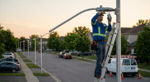
Most field problems with outdoor photocells trace back to installation decisions made on the day of fitting: the wrong wiring terminal, a sensor position facing the wrong direction, or a gasket that wasn’t seated before the housing was closed.
A photocell that is correctly specified but incorrectly installed will underperform or fail early. Getting these right at installation takes minutes. Fixing them later often means a maintenance visit at height.
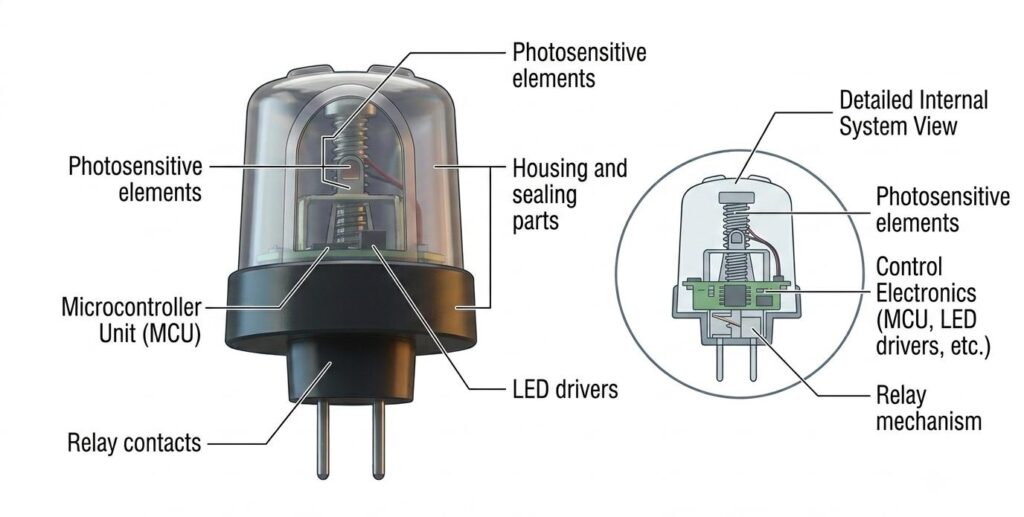
This guide covers the installation process and commissioning checklist for the Long-Join JL-103A wire-in photocell, one of the most widely used wire-in models for outdoor residential and commercial lighting.

What Should You Do Before Installation?
Three things need to be confirmed before touching any wiring:
- That the supply voltage matches the photocell’s voltage rating
- That the connected load stays within the ballast rated capacity
- That the installation position meets the waterproofing and exposure requirements.
The JL-103A is rated for 120VAC and carries a UL773A listing. It suits LED lamps, incandescent lamps, and various fixture types within its rated load. Prepare the following before you begin work:
- The correct wire gauge
- A screwdriver
- Electrical tape or approved connectors
- A voltage tester to confirm the circuit is dead before beginning work.
How Is the JL-103A Wired?

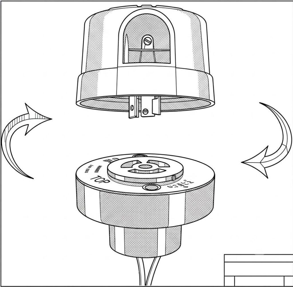
The JL-103A uses a standard three-terminal wiring configuration. Connect each wire to the correct terminal as shown on the manufacturer’s wiring diagram before making any connections.
| Terminal Name | Connection Description |
| Power Line Terminal (L) | Connects to the AC live wire |
| Neutral Line Terminal (N) | Connects to the AC neutral wire |
| Load Terminal | Connects to the lighting load |
| Ground Terminal (Optional) | Connects to ground if necessary for safety and interference protection |
Here are some other tips:
- Orient the sensor to face open sky (ideally north)
- Avoid positions next to reflective surfaces or in the direct beam of nearby street lights.
- Follow the manufacturer’s wiring diagram exactly
- Confirm each connection is secure before closing the housing.
What Should the Commissioning Checklist Cover?
Five inspection points should be verified before and after power is restored to the circuit.
| Inspection Item | Description |
| Power Disconnection Confirmation | Ensure power is disconnected before installation to prevent electric shock |
| Correct and Firm Wiring | Ensure terminal caps are secure, no loose or short circuits, and wire specs meet safety standards |
| Waterproof Sealing | Use waterproof sealing on connectors and materials to prevent water ingress into the photocell box |
| Exposure to Light for Sensor | Avoid obstruction during installation to guarantee accurate light sensing and prevent false light-off |
| Operational Testing | After the power connection, test the photocell switching sensitivity and load response under various light conditions |
What Are the Common Problems and How Are They Fixed?
Four issues account for most wire-in field problems, and each has a straightforward resolution.
Light Reflection
Light reflection causing false triggering is the most common problem a wire-in photocell faces. A nearby street light or reflective surface in the sensor’s field of view could cause the photocell to read artificial light as daylight and switch off mid-night. Adjusting the installation angle to move the sensor away from the reflected source resolves it.
Intermittent Wiring Connection
Intermittent wiring connection causes erratic switching behaviour that doesn’t follow a predictable pattern. Recheck all terminal connections, tighten any that have movement, and replace any corroded wires.
Overload-inducing Protection Trigger
When the connected load exceeds the JL-103A’s rated capacity, a protection is triggered by the overload. Check the total wattage of the connected fixtures and ensure it stays within the 500W tungsten-rated limit.
External Electromagnetic Interference
Nearby industrial equipment or power lines can produce electromagnetic interference, which causes unstable switching. Reliable grounding through the optional ground terminal and keeping wiring runs away from high-current conductors, where possible, improves stability.
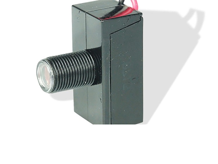
Installing a Wire-in Photocell
Correct installation of the JL-103A comes down to four things:
- Matching the supply voltage and load to the rated spec
- Wiring each terminal correctly according to the wiring diagram
- Positioning the sensor for unobstructed sky exposure away from artificial sources
- Verifying operation with the cover test before signing off on the installation.
Done correctly, the JL-103A delivers reliable dusk-to-dawn control with minimal maintenance for years of outdoor service.
Frequently Asked Questions on Photocell Installation
Q1: What types of lamps are suitable for the JL-103A photocell?
The JL-103A suits LED lamps, incandescent lamps, and various fixture types up to its rated load of 500W tungsten and 850VA ballast. It carries a UL773A listing for non-industrial photoelectric switching applications and is suitable for residential and light commercial outdoor lighting.
Q2: What is the most important step when installing a photocell?
Disconnecting the power before touching any wiring is non-negotiable. After that, correctly wiring to each terminal as shown on the manufacturer’s diagram and confirming the sensor is unobstructed are the two steps that prevent the majority of field problems.
Q3: Are there specific site suggestions for photocell placement?
Place the sensor where it has a clear view of open sky, ideally facing north, away from the light output of the connected fixture and any nearby artificial sources. Avoid positions under overhangs, next to reflective surfaces, or within the beam of adjacent street lights.
Q4: How do I test if the photocell works properly after installation?
Cover the sensor with a dark cloth or black tape and wait 30 to 60 seconds. The connected load should switch on within the time delay period. Remove the cover, and the load should switch off as the sensor reads the restored ambient light. This simulates nighttime conditions without waiting for actual dusk.
Q5: What are the common causes of photocell misoperation, and how are they fixed?
Some of the most common causes of photocell misoperation include:
- False triggering from reflected light. This can be fixed by adjusting the sensor angle away from the source.
- Intermittent operation from loose wiring. You can fix this by retightening all terminal connections.
- Overload protection triggering. This is fixed by reducing the connected load to within the rated capacity.
- Electromagnetic interference. This can be reduced through proper grounding and separating wiring runs from high-current conductors.