

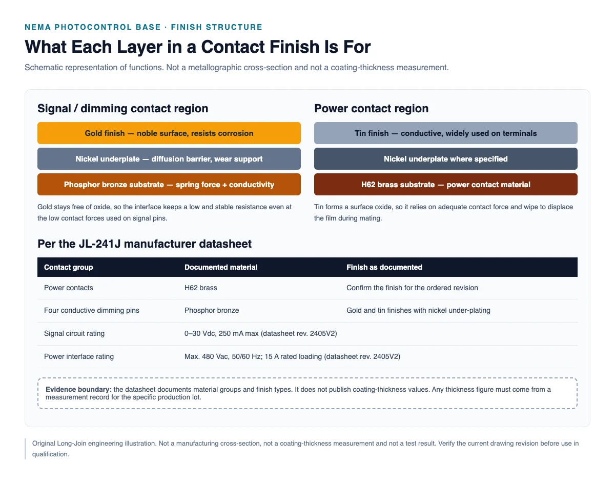
Quick answer. Gold-over-nickel plating separates three jobs that a single metal cannot do at once. The substrate — phosphor bronze or a brass — provides spring force and carries current. A nickel underplate acts as a diffusion barrier and a hard base, preventing the substrate from migrating into the surface and giving the soft gold mechanical support. The gold itself provides a contact surface that does not form an insulating oxide, so resistance stays low and stable even at low contact force. The finish only performs as a system: a thin, porous or uneven gold layer over an inadequate nickel layer behaves worse than its description suggests. And none of this is visible from the outside — plating quality can only be established by measurement records, not by appearance.
Why Does Contact Plating Matter in Outdoor Lighting Controllers?
A photocontrol base lives in an unusually hostile place for an electrical contact: outdoors, at height, in a sealed housing that breathes with every temperature cycle. Moisture enters on the cooling phase and condenses; airborne chloride, sulfur and dust arrive with it; and the assembly sits there for a decade or more without inspection.
At the contact interface, four processes run at once. Corrosion attacks any exposed base metal. Oxidation builds a resistive film on metals that are not noble. Fretting — small repetitive relative movement from vibration or thermal expansion — repeatedly breaks and reforms that film, generating oxide debris that accumulates at the contact spot. And wear from mating cycles removes the finish exactly where it is needed. Plating is the design answer to all four, which is why the finish specification matters as much as the contact geometry.
Contact force and plating are also coupled. A finish that resists oxide formation can work reliably at low normal force; a finish that oxidises needs higher force and more wipe to break through. Choosing a finish without reference to the spring design produces a contact that measures well on the bench and degrades in service.
What Is Gold-over-Nickel Plating?
What Does the Nickel Underlayer Do?
Nickel does two things that gold cannot do for itself. First, it is a diffusion barrier. Copper alloys and gold will interdiffuse over time, particularly at elevated temperature; copper reaching the surface oxidises and the contact resistance climbs even though the surface was gold. A nickel layer between them slows that migration. Second, nickel is hard. Gold is soft, and a soft coating on a soft substrate deforms and wears quickly under load; nickel gives the thin gold a supporting base so the coating survives contact pressure and sliding.
The underlayer is also a weak point when it is inadequate. If nickel is too thin, or porous, or poorly adherent, the barrier function fails at exactly the places where it is needed — and the resulting corrosion appears as small pits that grow into resistance drift. Thickness and porosity are process properties, verified by measurement, not by a certificate of composition.
Why Is Gold Used on Selected Contact Surfaces?
Gold’s value is narrow and specific: it does not form an insulating oxide in normal service atmospheres. That single property solves the film-resistance problem completely, which is why gold finishes are used where contact force is limited, where current is low, and where the signal must stay stable — signal and dimming contacts being the classic case. A 0–10 V control circuit has no thermal margin to spend on a resistive film, and its contact force is often modest.
Gold’s weakness is mechanical. It is soft, so it wears; it is expensive, so it is thin; and being thin, it can be porous. A gold finish is therefore always a compromise between thickness, cost and wear life, and the honest engineering statement about any gold contact is a specification plus a measurement, never a claim that gold “prevents corrosion”.
Why Does the Substrate Material Matter?
The substrate determines whether the contact can hold force and how well it conducts. It also determines what happens if the finish is breached: a substrate that corrodes aggressively will fail faster once exposed. Substrate choice is therefore a function of position in the connector, not a single company-wide preference. Spring positions need elastic behaviour; straight current-carrying positions need conductivity and formability.
Why Is Phosphor Bronze Used for Spring Contacts?
Phosphor bronze is a copper alloy with tin and phosphorus additions. The combination matters: it retains useful elastic behaviour and fatigue resistance through many deflection cycles, while keeping conductivity high enough for signal and moderate-power contacts. That is why it is used where a formed contact must apply and maintain force — the spring element of a connector.
Its limitation is thermal. Held at sustained elevated temperature, any copper-alloy spring gradually relaxes and loses part of its load. This is why an operating temperature range is a design constraint rather than a marketing figure, and why a contact that is correct at 25 °C may not hold its force at the top of its rated range.
It is not accurate to say phosphor bronze is better than other copper alloys in every application. Brasses offer higher conductivity at lower cost and are widely used for power contacts where a separate spring provides the force. Beryllium copper offers higher strength where it is permitted. The right statement is narrower and more useful: phosphor bronze is a good choice for spring positions in this class of connector, and a supplier should be able to say why a given position uses the material it does.
Gold vs. Tin Plating: Which Is Better?
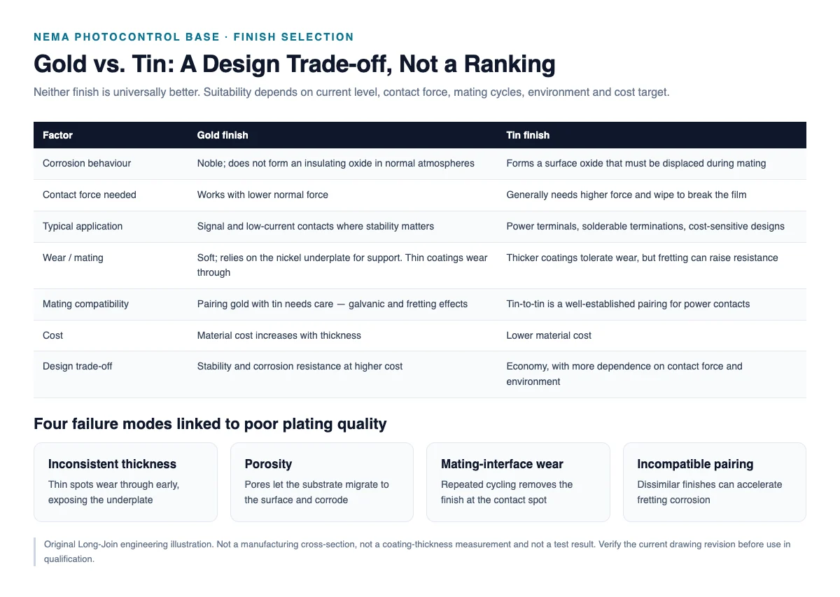
Neither is better in the abstract. They fail differently, and the correct choice depends on current, contact force, mating cycles, environment and cost target.
| Factor | Gold | Tin |
|---|---|---|
| Corrosion behaviour | Noble; no insulating oxide in normal atmospheres | Forms a surface oxide that must be displaced mechanically |
| Contact application | Signal, low current, low force, stability-critical circuits | Power terminals, solderable terminations, general connections |
| Cost considerations | Material cost rises steeply with thickness | Low material cost; thick coatings are affordable |
| Wear and mating | Soft; relies on the nickel underplate. Thin coatings wear through to nickel | Thicker coatings tolerate wear, but fretting corrosion is the characteristic risk |
| Surface compatibility | Gold-on-gold is the most predictable pairing; gold against tin needs evaluation | Tin-on-tin is well established for power contacts |
| Typical design trade-off | Stability and corrosion margin, paid for in cost and wear sensitivity | Economy and robustness, paid for in contact force and fretting sensitivity |
The pairing question deserves emphasis because it sits outside any single supplier’s control. A base and a receptacle made by different manufacturers may use different finishes. Gold mated with tin is not forbidden, but the interface now has a noble-to-base-metal couple, and in the presence of moisture that changes the corrosion behaviour and the failure mode. Buyers evaluating a base should ask what finish the mating receptacle uses, and test the pair.
What Can Go Wrong With Poor Plating Quality?
Inadequate or Inconsistent Coating Thickness
Plating thickness varies across a part by nature — edges and high-current-density areas build faster, recesses slower. When the process is poorly controlled, thin regions appear exactly where contact occurs. A thin gold layer wears through early; a thin nickel layer fails as a barrier; a thin tin layer oxidises through. The failure is not a sudden break but a gradual resistance rise that only appears after cycling or after months in the field.
Porosity and Exposed Underlying Material
Thin coatings, and coatings deposited on a poorly prepared surface, contain pores. Through a pore, the substrate or the underplate is exposed to the atmosphere and to the mating surface. Corrosion starts in the pore, corrosion products spread across the contact area, and resistance climbs. Porosity is a process property — it depends on surface preparation, bath chemistry and thickness — and it cannot be judged visually.
Wear at the Mating Interface
Each mating cycle slides the surfaces and wipes the finish at the contact spot. The spot is small, so the wear is concentrated. Gold wears through to nickel, nickel oxidises slowly, and resistance rises. Debris from wear accumulates in the same place. Where the design has low contact force, that debris is not displaced and the effect compounds.
Incompatible Contact Pairing
Dissimilar finishes in a humid environment form a galvanic couple. The less noble metal corrodes preferentially, and the corrosion products collect at the interface. This is a system-level failure that neither supplier will see in their own testing unless the pair is tested together — which is the practical argument for qualifying the base and the receptacle as a matched interface.
JL-241J Contact Construction Explained
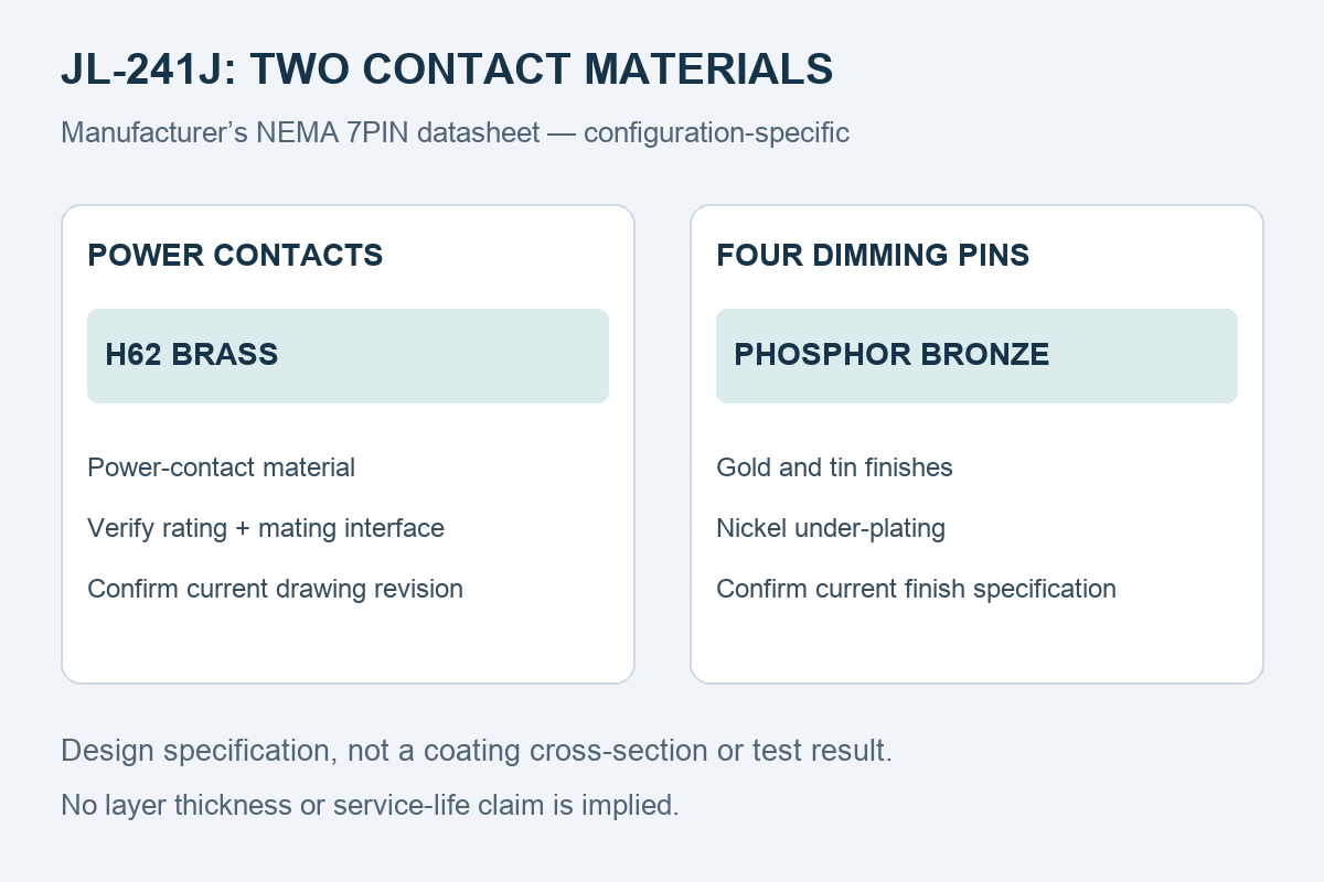
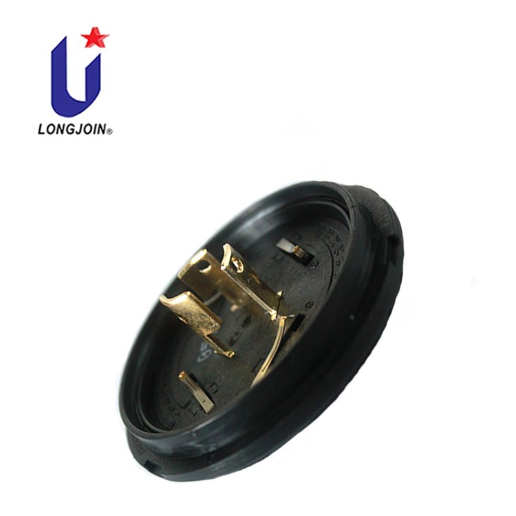
Long-Join’s documentation for the JL-241J NEMA 7-pin base distinguishes two contact groups rather than describing one finish for the whole part:
- Power contacts: H62 brass substrate.
- Four conductive dimming pins: phosphor bronze substrate, with gold and tin finishes over nickel under-plating.
That differentiation is the engineering point. Power contacts carry the load current and benefit from a higher-conductivity, lower-cost brass with a robust finish. The four dimming pins carry a low-level control signal where a stable, oxide-free surface matters more than conductivity, which is why a phosphor bronze spring with a gold finish appears there. Reading the datasheet as “the base is phosphor bronze, gold plated” would misstate both the material and the reason for it.
What the documentation does not provide is equally important. It does not publish coating thickness values, it does not publish a cross-sectional measurement, and it does not publish a plating specification expressed in microns. Those are production-lot properties, verified by measurement. This article does not supply them, does not estimate them, and does not compare them with any other manufacturer’s coating. A statement that a coating matches another company’s thickness would require a measurement comparison that has not been made.
Product information: JL-241J NEMA photocontrol base. Material and assembly documents: 7-pin material datasheet and electrical assembly specification, rev. 2405V2.
How Can Buyers Verify Plating Quality?
Plating quality is a process claim, and process claims are verified by records. The document set below is what a buyer should hold before approving a finish specification.
| Document or data | What it establishes | Why it cannot be replaced by a visual check |
|---|---|---|
| Plating specification | Finish type per contact region, over the specified underplate | Appearance says nothing about layer order or thickness |
| Material grade | Substrate alloy for each contact group | Brass and phosphor bronze look identical when plated |
| Thickness measurement records | Actual coating thickness on production parts | The only evidence that the process holds the specification |
| Corrosion test conditions and results | Behaviour under a defined exposure | Time in a chamber is a method, not a service life |
| Mating durability results | Finish behaviour after repeated cycles | Wear-through only appears after cycling |
| Contact resistance results | Electrical consequence of the finish system | The property that actually matters at the interface |
On measurement technique: X-ray fluorescence (XRF) is widely used for coating thickness on small parts because it is fast and non-destructive, and it is commonly combined with micro-section examination where layer structure must be confirmed. Its applicability depends on the coating system and the substrate — thin layers over a similar-element underplate need appropriate calibration, and results should be interpreted by someone who knows the method’s limits. This article does not state which instrument Long-Join uses for production control; that is a question to put to the supplier directly.
Does a Salt Spray Test Prove Long-Term Reliability?
No. Salt spray is a comparative screening method, not a life prediction. A chamber applies one aggressive condition continuously; the field applies wetting and drying, pollution, UV, electrical load and mechanical movement. Passing 96 hours says the finish system survived 96 hours of that method — useful when comparing two candidate finishes under identical conditions, unreliable when converted into “X years outdoors”.
What makes a salt-spray result meaningful is the method statement: the standard and edition, the salt concentration and chamber temperature, whether the sample was mated or unmated, whether it was energised, how it was cleaned, and what counted as a failure. Without those, the duration alone is a number without a scale.
Frequently Asked Questions
Why is nickel used under gold plating?
Because gold alone cannot stop the substrate from reaching the surface. Nickel acts as a diffusion barrier between a copper alloy and the gold, and it is hard enough to support a thin, soft gold layer under contact pressure. Without an adequate underplate, gold thickness buys less durability than its specification suggests, and corrosion products from the substrate can appear at the interface.
Is thicker gold plating always better?
Not automatically. Thicker gold improves wear margin and reduces porosity, but it costs more and does not fix an inadequate nickel underlayer, poor surface preparation, insufficient contact force or an incompatible mating finish. Thickness is one variable in a system, and a thickness figure without a measurement record and a defined underplate says little about field behaviour.
What is the difference between gold and tin contacts?
Gold does not form an insulating oxide, so it holds a stable low resistance at low force and low current — useful for signal circuits. Tin forms a surface oxide that must be mechanically displaced, so it needs adequate contact force and wipe; it is economical, robust when thick, and well established for power terminals. They fail differently: gold by wear-through, tin by oxide film and fretting corrosion.
Can poor plating increase contact resistance?
Yes, through three routes: a resistive film on a finish that oxidises, exposure of an underplate or substrate through pores and worn areas, and accumulation of corrosion or wear debris at the contact spot. In each case the resistance rises gradually rather than failing suddenly, which is why post-conditioning measurements reveal problems that initial readings hide.
What coating documentation should OEM buyers request?
The plating specification per contact region with the underplate stated; the substrate alloy grade; thickness measurement records for production parts; corrosion test conditions and results; mating durability results; and contact resistance values before and after conditioning. Ask also for the drawing revision the specification applies to, so that the documents describe the parts you will actually receive.
Key Takeaways
Gold-over-nickel is a three-part system: substrate for force and conduction, nickel for barrier and mechanical support, gold for an oxide-free surface. Each layer fails in a characteristic way, and the whole system can only be verified by measurement. Phosphor bronze is chosen for spring positions because it holds force, not because it is universally superior; power positions commonly use a brass. Gold and tin are a trade-off, not a ranking, and the pairing with the mating receptacle is part of the design. On the JL-241J, the manufacturer documents H62 brass power contacts and phosphor bronze dimming pins with gold and tin finishes over nickel under-plating — and does not publish coating thickness values, which is exactly why a buyer should ask for measurement records rather than accept a description.
Request JL-241J contact material and plating information.
Tell us the contact positions and environment that matter for your design. We will confirm the documented material and finish for that configuration and indicate which items require a measurement record.
- Order code and contact positions of interest
- Rated current and signal type at each position
- Environment: coastal, industrial, humidity, temperature range
- Mating receptacle finish, if already selected
- Documentation you require for qualification
References and Technical Sources
- Long-Join JL-241J NEMA 7-pin material datasheet — contact material groups and finish types.
- Long-Join JL-241J electrical assembly specification, rev. 2405V2 — published electrical ratings.
- Long-Join JL-241J product page — configuration and ordering information.
- Why Do Contact Resistance and Plating Quality Matter in NEMA Photocontrol Bases? — the contact-interface mechanism in detail.
- How to Evaluate the Reliability of a NEMA Photocontrol Base Before Bulk Purchasing — pillar guide.
- IEC 60068-2-11:2021, Environmental testing — Part 2-11: Tests — Test Ka: Salt mist — cited by designation and edition; consult the published scope for applicability.
- ANSI C136.41-2025 — interface requirements for external locking-type controls and roadway or area luminaires.



One Response