Technical Guide | NEMA Photocontrol Components | OEM Supplier Qualification
Quick Answer: What Should Buyers Check?
Before purchasing a NEMA photocontrol base in bulk, buyers should evaluate four critical reliability factors: mating and unmating durability, contact resistance, temperature rise under rated current, and corrosion resistance. These characteristics influence electrical connection stability, operating safety, and long-term performance.
A reliable supplier should be able to explain its contact materials, plating structure, applicable UL certification, and qualification methods. Buyers should also request product-specific test reports rather than relying only on general claims of standards compliance.
For lighting-control OEMs, the most important question is not simply whether a base is compatible with a NEMA interface, but whether its electrical and mechanical performance can be verified under the intended operating conditions.
1. Why Does NEMA Photocontrol Base Reliability Matter?
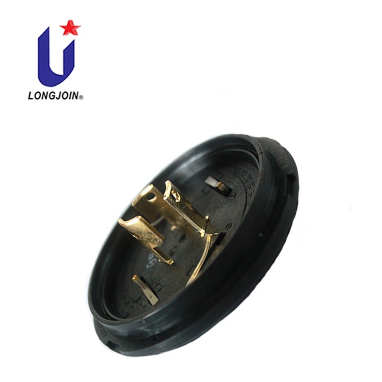
A NEMA photocontrol base forms the electrical and mechanical connection between a lighting controller and its mating receptacle.
Although the base is relatively small, its contacts must maintain stable electrical performance during installation, operation, environmental exposure, and potentially repeated servicing.
Poor contact performance may cause localized heating, intermittent electrical connections, voltage drops, or premature deterioration.
For street-lighting controller manufacturers, these failures can lead to product returns, warranty claims, additional field service, and delays in customer qualification.
Reliability becomes particularly important when a controller is intended for large-scale municipal street-lighting deployment.
A manufacturer evaluating 10,000 or 50,000 controller assemblies should therefore examine the quality of the connection interface before approving a base for volume production.
NEMA Photocontrol Base vs. NEMA Receptacle
The two components perform different roles.
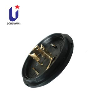
The photocontrol base is typically part of the removable controller assembly. It carries the controller-side terminals and provides the locking interface.
The NEMA receptacle is generally installed on the luminaire and provides the mating electrical contacts.
Both components contribute to connection reliability.
A well-designed photocontrol base cannot compensate for an incompatible, damaged, or poorly manufactured mating receptacle.
For engineering qualification, the base and receptacle should be evaluated as a matched interface.
2. Mating and Unmating Durability: Will the Contacts Remain Stable?
Mating and unmating durability evaluates whether the connector interface can maintain acceptable mechanical and electrical performance after repeated connection cycles.
Each installation or removal cycle places mechanical stress on the contacts and locking features.
Potential failure mechanisms include:
- Permanent deformation of spring contacts.
- Loss of contact force.
- Damage or wear to the plating.
- Increased contact resistance.
- Mechanical damage to the base or locking interface.
How Many Mating Cycles Should a NEMA Photocontrol Base Withstand?
There is no universal cycle count that buyers should assume applies to every NEMA photocontrol base configuration.
Some OEM qualification programs may request 100 or 200 cycles. However, these figures should not automatically be described as mandatory requirements of ANSI C136.41.
The applicable acceptance criteria must be confirmed against the relevant standard edition, connector configuration, and customer qualification specification.
Buyers should ask suppliers to specify:
- The number of completed mating and unmating cycles.
- The mating receptacle used for the test.
- Whether electrical measurements were taken before and after cycling.
- The criteria for spring deformation and contact wear.
- The resulting contact resistance and mechanical inspection results.
Engineering recommendation: Evaluate both mechanical condition and electrical performance after durability testing. A connector may still be physically operable while its contact performance has deteriorated.
3. Contact Resistance: Why Can a Small Resistance Increase Cause Problems?
Contact resistance measures the electrical resistance at the mating contact interface.
Excessive resistance can result from insufficient contact force, contamination, corrosion, worn plating, or an unsuitable contact structure.
When electrical current passes through a resistance, heat is generated.
The relationship can be expressed as:
P = I²R
Where:
- P = heat dissipation in watts
- I = electrical current in amperes
- R = electrical resistance in ohms
For example, at a hypothetical current of 15 A, a contact resistance of 10 mΩ produces approximately 2.25 W of resistive heating.
At 20 mΩ, the calculated heat generation increases to 4.5 W.
These calculations illustrate the electrical principle only. They are not measured JL-241J values, and 15 A should not be interpreted as a confirmed current rating of every JL-241J terminal.
Actual temperature rise depends on contact geometry, thermal conduction, enclosure conditions, current path, and other factors.
What Contact Resistance Data Should Buyers Request?
A useful supplier qualification report should identify:
| Test Information | Why It Matters |
|---|---|
| Initial contact resistance | Establishes the baseline electrical performance |
| Resistance after mating cycles | Indicates potential contact wear or loss of contact force |
| Resistance after environmental exposure | Helps evaluate corrosion-related degradation |
| Test current and measurement method | Makes results technically comparable |
| Maximum permitted resistance or resistance change | Defines the pass/fail criterion |
For low-resistance measurements, the test method and fixture should be documented. Four-terminal measurement techniques can help reduce measurement errors caused by test leads and connections.
Buyer recommendation: Do not approve a connector based only on a claim of “low contact resistance.” Request the actual measured values, test conditions, and acceptance criteria.
4. Temperature Rise: How Does Current Affect Contact Safety?
Temperature-rise testing evaluates how much the temperature of an electrical contact increases when current flows through it.
The temperature rise is calculated as:
ΔT = Contact Temperature − Reference Ambient Temperature
Elevated temperature at a connection may indicate excessive contact resistance, inadequate contact pressure, insufficient conductive material, or unsuitable thermal design.
A temperature-rise test should be performed under clearly defined electrical and environmental conditions.
Is a 30°C Temperature-Rise Limit Always Required?
A maximum temperature rise of 30°C at a specified current is a technical criterion encountered in some connector specifications and procurement requirements.
However, a buyer should not assume that 15 A and a 30°C maximum temperature rise apply to every terminal of every photocontrol base.
The correct test conditions depend on the relevant standard, rated contact type, mating interface, and product configuration.
For a controller base with power contacts and low-voltage signal contacts, the electrical ratings and evaluation requirements may differ.
What Should a Temperature-Rise Report Include?
The report should identify the tested current, ambient temperature, contact measurement locations, test duration or stabilization criteria, mating receptacle, and maximum recorded temperature rise.
It should also identify which terminals were energized.
Engineering recommendation: Request temperature-rise data for the actual power-contact configuration and intended operating current. Do not substitute a signal-contact rating or an unrelated connector report.
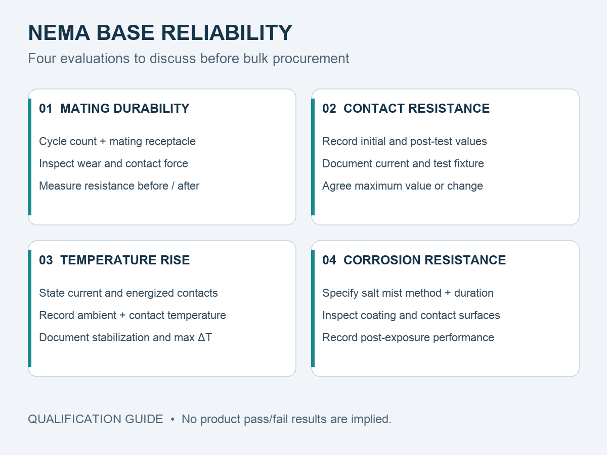
5. Salt Spray and Contact Plating: How Can Buyers Assess Corrosion Resistance?
Outdoor lighting equipment may be exposed to humidity, condensation, salt-laden air, industrial pollutants, and temperature changes.
Metal contacts can deteriorate when their protective plating is damaged or when corrosive substances reach susceptible underlying material.
Corrosion can affect contact resistance and long-term connection stability.
What Is the Function of Nickel, Gold, and Tin Plating?
Different plating materials serve different functions.
Nickel plating can provide a protective barrier between the copper-alloy substrate and the outer contact finish.
Gold plating provides a corrosion-resistant contact surface and can help maintain electrical contact performance when applied with suitable thickness and processing controls.
Tin plating is commonly used on electrical terminals because of its conductive properties and established use in connector systems. Its performance depends on the mating interface, contact force, wear conditions, and environmental exposure.
Plating selection should therefore consider the complete connector design rather than one material in isolation.
A Practical Plating Example: Long-Join JL-241J
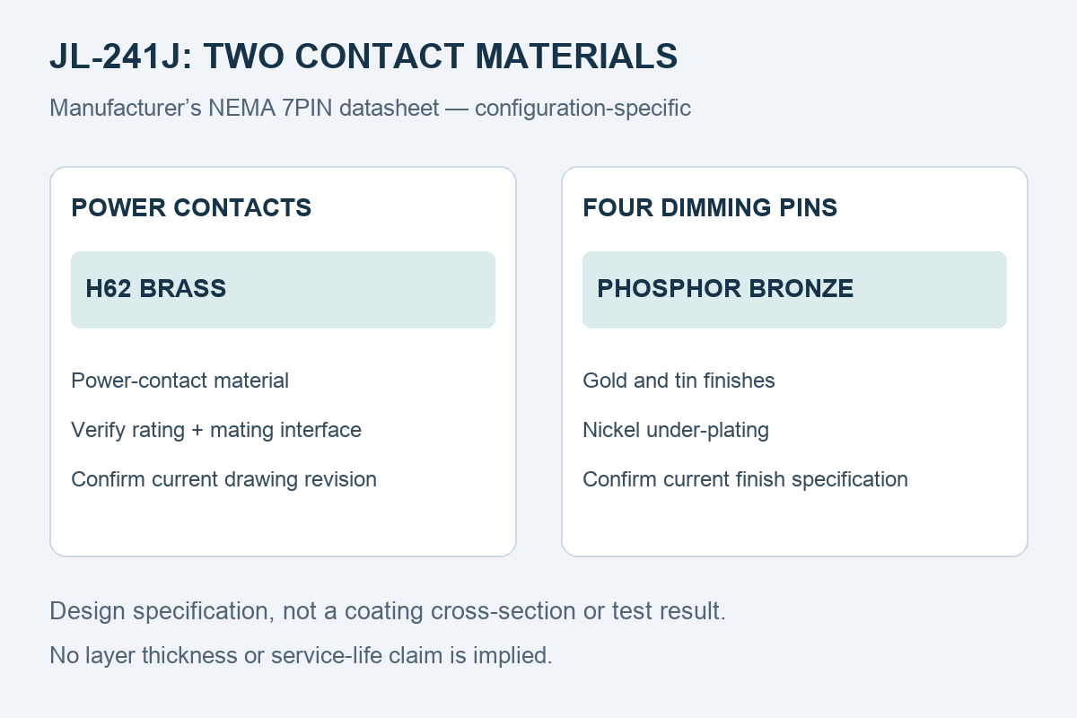
The manufacturer’s DATASHEET of NEMA 7PIN JL-241J distinguishes two contact types: H62 brass for the power contacts, and phosphor bronze for the four conductive dimming pins. The signal-pin description specifies gold and tin finishes with nickel under-plating. It does not mean that every contact in the base is phosphor bronze.
These are manufacturer design specifications for the documented configuration, not coating-thickness measurements. Confirm the current order code, drawing revision and finish specification before approving production. No coating thickness or current-production finish-region claim is made here.
Learn more: Long-Join JL-241J NEMA Photocontrol Base
Does Passing a 48-Hour or 96-Hour Salt Spray Test Guarantee Outdoor Reliability?
No.
Salt spray testing is a useful method for assessing comparative corrosion resistance and the quality of protective coatings.
IEC 60068-2-11:2021 describes a salt mist test method for electrotechnical products, components, and materials.
However, test duration alone does not establish a universal outdoor service life.
A complete corrosion assessment should consider:
- The applied test standard and method.
- Exposure duration.
- Sample configuration.
- Coating condition before and after testing.
- Visual inspection criteria.
- Electrical measurements after exposure, where applicable.
- The real operating environment.
For coastal or highly corrosive environments, a customer may also specify additional or cyclic environmental testing.
Buyer recommendation: Request the exact test method, exposure duration, inspection criteria, and results. Do not treat a generic “salt spray passed” statement as sufficient evidence.
6. UL Recognition and ANSI C136.41: What Do They Actually Verify?
UL component recognition and ANSI interface standards address different aspects of product qualification.
What Does UL Recognized Component Mean?
UL Recognized Component certification applies to components intended for integration into larger products or systems.
According to UL Solutions, recognized components are evaluated against applicable requirements under specified conditions of acceptability.
These conditions may affect how a component can be used in a finished product.
UL Recognition is valuable when qualifying a photocontrol base for incorporation into a lighting controller.
However, it does not automatically establish that every customer-requested durability, temperature-rise, or corrosion test has been completed under the buyer's specified conditions.
The relevant UL file, exact model coverage, ratings, and conditions of acceptability should be reviewed.
What Does ANSI C136.41 Cover?
ANSI C136.41-2025 addresses the interface between external locking-type controls and roadway or area luminaires for dimming and related functions.
The standard covers mechanical, electrical, and marking aspects of the control interface.
Its published scope includes 0–10 V and DALI dimming protocols and incorporates applicable ANSI C136.10 requirements unless specifically superseded.
For engineering qualification, buyers should verify both interface compatibility and the applicable product certification documentation.
Why Is Product-Specific Evidence Important?
A product family may include different terminal counts, contact configurations, ratings, and materials.
Evidence for one configuration should not automatically be applied to another.
Before approving a supplier, ask whether the provided certificate or test report covers the exact product model and revision being purchased.
7. What Should Buyers Verify in the Long-Join JL-241J Base?
The Long-Join JL-241J product family is intended for use in photocontrol and smart lighting-controller assemblies.
The official product page identifies several features, including:
- PBT base material.
- UL94 V-0 flame-rating specification.
- A sealing arrangement that must match the approved assembly drawing.
- NEMA/ANSI C136.41 interface compatibility.
- JL-241J documentation covering 5-pin and 7-pin controller configurations; confirm the exact order code.
These features provide a starting point for technical evaluation, but the exact configuration should be confirmed before purchasing.
Documented Ratings and Evidence Boundaries
The manufacturer’s JL-241J English datasheet, revision 2405V2, lists the following design ratings. They are not a substitute for sample-specific reliability results.
| Item | Manufacturer specification | Qualification condition |
|---|---|---|
| Power interface | Max. 480 Vac, 50/60 Hz; 15 A rated loading | Confirm the exact assembly and contact path. A 15 A rating is not a measured temperature-rise result. |
| Signal control | 0–30 Vdc; 250 mA max. | Do not apply power-contact ratings to signal contacts. |
| Base and ambient | PBT; −40°C to +70°C | Confirm the current material grade and assembly requirements. |
| Ingress protection | IP66 reachable after assembly | This is an assembly-dependent specification, not a bare-base IP66 test claim. |
Series testing: ZICS report 2475771-3, issued 21 November 2024, includes JL-241J in its model scope and identifies JL-242JV, JL-240X and JL-260D as representative test samples. The report updates report 2217271 of 9 May 2022. Representative-model results must not be relabelled as independent JL-241J measurements, or counted as two independent test campaigns.
UL documentation: A manufacturer-held historical UL directory record, printed 26 March 2019 and updated 20 February 2019, includes JL-241J and JL-241JF under WJFX2.E188110. This establishes historical model inclusion only. Ask for the current model scope and conditions of acceptability; this article does not certify current online status.
Four-test qualification: The documents reviewed do not establish a complete set of independent JL-241J sample results for mechanical mating life, initial/post-cycle resistance, rated-current temperature rise and salt spray. This does not mean that JL-241J has never been evaluated. Request exact sample identities, representative coverage and applicable test records.
Download the JL-241J 7-pin material datasheet (manufacturer document) · Download JL-241J electrical and assembly specifications, 2405V2
JL-241J Technical Qualification Checklist
| Evaluation Item | Information to Verify |
|---|---|
| Controller interface | Exact NEMA mating configuration |
| Housing | PBT material grade and drawing |
| Terminal construction | Contact substrate and plating specification |
| Mating durability | Cycles, inspection criteria, and test results |
| Contact resistance | Initial and post-test measured values |
| Temperature rise | Rated current, maximum ΔT, and test setup |
| Corrosion resistance | Salt spray method, duration, and results |
| UL documentation | Applicable file, model coverage, and conditions |
| Engineering documentation | 2D drawings, 3D models, and revision control |
For Long-Join JL-241J, buyers should request the relevant product-specific documents directly rather than assume that any unpublished test values are available or have been verified.
Product reference: JL-241J Photocontrol Base – Long-Join
8. How Should OEM Buyers Qualify a Photocontrol Base Supplier?
For repeated production orders, supplier qualification should cover more than the initial sample appearance.
Step 1: Confirm Mechanical Compatibility
Obtain the dimensional drawing and confirm the required locking interface, terminal arrangement, and mating receptacle.
If the supplier provides 3D models, verify whether STEP or other neutral CAD formats are available for engineering integration.
Step 2: Review Electrical Performance
Confirm the ratings of the power contacts and signal contacts separately where applicable.
Check available contact resistance and temperature-rise evidence.
Step 3: Review Materials and Plating
Ask for material specifications, plating construction, specified coating thickness, and applicable inspection methods.
Step 4: Review Certification Coverage
Check that the applicable certificate covers the exact model or variant and its intended operating conditions.
Where UL Recognition is relevant, verify the manufacturer's documentation and applicable conditions of acceptability.
Step 5: Request Qualification Samples
For a new supplier or modified contact design, consider a qualification plan involving:
- Dimensional inspection.
- Mating and unmating evaluation.
- Contact resistance measurement.
- Temperature-rise evaluation.
- Environmental testing where required.
The test scope and acceptance criteria should be agreed upon before production approval.
Step 6: Confirm Production Consistency
For ongoing supply, buyers may also request information about material traceability, inspection records, process changes, and drawing revision control.
A well-documented supplier evaluation process helps reduce the risk of approving a sample that is not representative of later production.
9. Frequently Asked Questions
Q1. How many mating cycles should a NEMA photocontrol base withstand?
The required number depends on the applicable standard and OEM qualification specification. Buyers should not assume that 100 or 200 cycles are universally mandatory. Request the actual test conditions, cycle count, and post-test results.
Q2. What contact resistance is acceptable for a photocontrol base?
The acceptable contact resistance depends on the contact design, intended current, applicable specification, and measurement method. Buyers should obtain the initial resistance and the maximum permitted value or change after relevant qualification tests.
Q3. Can high contact resistance cause a photocontrol base to overheat?
Yes. Electrical resistance generates heat when current passes through the connection. The amount of resistive heating increases with the square of current, so contact quality is particularly important in higher-current power interfaces.
Q4. Does UL Recognized mean a photocontrol base has passed all reliability tests?
No. UL Recognition establishes compliance with applicable component requirements under defined conditions. It does not automatically confirm that the product meets every additional OEM-specific durability or environmental test requirement.
Q5. Is gold plating better than tin plating for every electrical contact?
Not necessarily. Gold and tin finishes have different performance characteristics, costs, and mating requirements. The suitable finish depends on the contact structure, operating environment, current, contact force, wear, and mating material.
Q6. Can buyers request CAD files and test reports before bulk ordering?
Yes. OEM buyers should request available 2D drawings, 3D exchange files, material specifications, certification documents, and relevant qualification reports. Document availability may depend on the model, project requirements, and confidentiality arrangements.
10. Key Takeaways
Reliable NEMA photocontrol base sourcing requires more than confirming mechanical compatibility or reviewing a UL claim.
Before bulk purchasing, evaluate the mating interface, contact resistance, temperature rise, contact materials, plating construction, and corrosion resistance. Request actual test conditions and acceptance criteria rather than accepting unsupported statements.
For OEM qualification, verify that certificates, test reports, and drawings cover the exact product configuration being purchased. Long-Join JL-241J provides a practical example of a NEMA photocontrol base that can be evaluated through this process.
A well-documented component qualification process can help lighting-controller manufacturers reduce integration risk and make more consistent purchasing decisions.
Technical Consultation: Evaluate Your NEMA Photocontrol Base Requirements
If you are developing or sourcing photocontrol assemblies for outdoor LED street lighting, contact CHI-SWEAR to discuss Long-Join base configurations and the documentation available for your project.
To make the engineering review more efficient, please provide:
- Required 3-pin, 5-pin, or 7-pin interface.
- Intended controller application and mating receptacle.
- Power-contact current and voltage requirements.
- Environmental conditions and corrosion requirements.
- Required UL documentation and reliability tests.
- Estimated annual purchasing volume.
Review the product: Long-Join JL-241J NEMA Photocontrol Base
Request JL-241J Technical Documents & Qualification Support
Specify “JL-241J Technical Evaluation” and include your company email, required configuration, current, voltage, qualification tests, and estimated purchasing volume.
Related components: Browse CHI-SWEAR NEMA photocontrol components.
References and Technical Sources
- Long-Join – JL-241J NEMA Photocontrol Base
https://long-join.com/product/nema-5-pin-photocell-base-jl-241j/
- ANSI C136.41-2025 – Roadway and Area Lighting Equipment: Dimming Control Between an External Locking Type Photocontrol and Ballast or Driver
https://webstore.ansi.org/standards/nema/ansic136412025
- UL Solutions – Components Certification
https://www.ul.com/industries/components
- UL Solutions – The UL Component Recognition Classification
https://www.ul.com/thecodeauthority/knowledge/ul-component-recognition-classification
- IEC 60068-2-11:2021 – Environmental Testing, Test Ka: Salt Mist
https://webstore.iec.ch/en/publication/64484
Editorial verification note: Manufacturer design ratings, historical certification records and representative-sample testing are distinct evidence types. No unverified JL-241J mechanical cycle count, measured contact resistance, measured temperature rise, coating thickness, salt spray duration or service-life claim is presented here. Confirm current-production documents for the exact order configuration.