
OUTLINE
Q2: How can photocells avoid false triggers from external light interference?
- Introduction
- What Is On-Off Cycling and Where Does It Appear?
- What Are the Top Ten Causes of On-Off Cycling in Motion Sensors?
- What Are the Main Causes of Photocell On-Off Cycling?
- How Do Photocell and Motion Sensor Faults Compare for Diagnosis?
- Preventing On-Off Cycling Issues
- Frequently Asked Questions on On-Off Cycling
Repeated switching can disrupt lighting and increase switching stress. Determine whether the behaviour is intended occupancy control or an unintended fault before changing settings.
Outdoor lighting may use a photocontrol, a motion sensor or a combined controller. Diagnose the selected control function, driver and installation together.
Diagnosing the right cause saves a lot of time on site.

What Is On-Off Cycling and Where Does It Appear?
On-off cycling is a fault where a lamp repeatedly switches between on and off states in a pattern that doesn’t correspond to true changes in ambient light or occupancy.
It commonly appears in outdoor lights such as street lights, parking lot lights, high mast lights, and warehouse perimeter lighting, as well as any application where a motion sensor or photocell is the primary control.
The impact is threefold:
- Energy waste from unnecessary switching events
- Accelerated wear on both the relay contacts in the photocell and the LED driver in the fixture
- Negative user experience that generates complaints and service calls.
What Are the Top Ten Causes of On-Off Cycling in Motion Sensors?
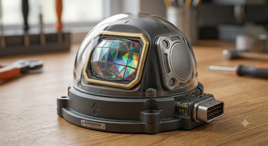
Potential causes depend on sensing technology and installation. The following table is a checklist for investigation, not a diagnosis applicable to every sensor.
Here are 10 common causes and their impact.
| Main Cause | Description | Impact |
| Excessive False Triggers | Investigate unintended detection within the actual sensing field; response varies by sensing technology and site conditions. | Frequent flickering due to false activation |
| Too Short Delay Setting | Check the documented hold time and retrigger settings against the site occupancy pattern. | Rapid switching causing cycling |
| Oversized Detection Area | Compare the actual detection field and mounting position with the intended occupancy area; triggers depend on sensing technology. | Abnormal cycling harming stability |
| Incorrect Installation | Verify mounting height, orientation and environmental exposure against the selected model instructions. | Erroneous sensing or environmental interference causing cycling |
| Incompatible Driver | Frequent switching causes transient surges, protection mode triggered, false status of motion sensor | Lamps continuously cycle on/off due to multiple faults |
| Extreme Temperatures | Winter temperature difference or summer heat increases sensor noise | False triggers increasing, reducing system stability |
| Infrared Interference | Inspect the PIR window, temperature changes and external heat sources according to the model troubleshooting guidance. | Sensor misjudgment impacts normal usage |
| Unstable Power Supply | Voltage fluctuations cause motion sensor reboot, leading to a cycle | Flickering caused by frequent power cycling |
| Sensor Aging | Sensitivity drift, delay failure, frequent false triggers, MCU error | Requires replacement, causing long-term instability |
| Insect Blocking Sensor | Inspect the sensor window for contamination or obstruction; the resulting behaviour depends on the model. | Continuous light, lamp remains on without switching |
Check the specified hold time and retrigger behaviour for the selected controller. A short hold time may cause repeated occupancy-driven switching, which is not necessarily a device fault.
For a car park, validate hold time against occupancy, the required lighting level and the site control plan. Change settings only within the documented range; no single 30–60 second setting resolves every cycling issue.
What Are the Main Causes of Photocell On-Off Cycling?
For photocontrols, investigate light feedback, sensor obstruction, thresholds, supply, load and the mating receptacle. The checklist does not exclude other faults.
| Cause | Details | Problem Triggered |
| Abnormal Light Source | Strong environmental light or stray emissions from adjacent lamps or car lights | Erroneous switching of photocell |
| Installation Position | Follow the model installation instructions; keep the sensor clear of the fixture’s own light and reflected artificial light. | Misalignment causes judgment errors |
| Incompatible Driver | Electrical incompatibility leads to abnormal signals | Photocell acts erratically |
| Photocell Window Blockage | Dirt, moisture blocks light sensor surface | Insufficient sensing, high mistriggers |
| Socket Wiring Errors | Wiring mismatch causing photocell malfunctions | Abnormal and fluctuating function |
The most common photocell cycling scenario is the self-illumination feedback loop:
- The fixture’s own light output reaches the sensor
- This raises the lux reading above the off-threshold
- This switches the light off
- The lux drops, and switches the light back on
- The cycle repeats.
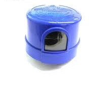
Reduce light feedback by following the model-specific sensor orientation and keeping the sensor away from the fixture’s own light and reflections. For twist-lock photocells, confirm the sensor window and orientation in the selected model instructions; a NORTH direction is not a universal requirement for every controller.
How Do Photocell and Motion Sensor Faults Compare for Diagnosis?
Identify every device controlling the fixture, record the switching pattern and compare it with the model instructions. Check the supply and load compatibility as well as light or occupancy inputs; a system may contain more than one cause.
Use the following comparison to choose checks for each control function. Diagnostic difficulty depends on the actual system and available documentation.
| Comparison | Photocell Faults | Motion Sensor Faults | Remarks |
| Fault Detection | Check light feedback, thresholds, delay, supply and load compatibility. | Check sensing technology, detection area, hold time, supply and load compatibility. | Use the model fault procedure; the control type alone does not determine diagnostic difficulty. |
| Environmental Resistance | Check the model temperature range, ingress protection and installation requirements. | Check the model temperature range, ingress protection and installation requirements. | Compare documented performance under equivalent conditions; durability is model-specific. |
| Source of Interference | Natural and artificial light, reflections, obstruction and electrical conditions may affect operation. | Potential triggers depend on sensing technology, detection field and the installation environment. | Assess the selected sensing technology and site conditions; do not assume all motion sensors respond alike. |
Preventing On-Off Cycling Issues
On-off cycling is a diagnosable and fixable fault in both motion sensors and photocells, but the two device types produce it through very different mechanisms. Long-Join’s IR-filtered, time-delay-equipped photocell range minimises the cycling risk that poorer-specified units produce, and combined sensor products like the JL-723A1H provide adjustable parameters that address the most common motion sensor cycling causes directly.
Frequently Asked Questions on On-Off Cycling
Q1: What causes frequent on-off cycling in motion sensors?
The ten most common causes of on-off cycling are:
- Excessive false triggers from small animals or weather
- Too-short delay settings
- Oversized detection area
- Incorrect installation position
- LED driver incompatibility
- Extreme temperatures
- Infrared interference from rain or fog
- Unstable power supply
- Sensor aging
- Insect blockage of the PIR window.
Delay setting and installation position are the most commonly correctable causes.
Q2: How can photocells avoid false triggers from external light interference?
Follow the selected model’s orientation instructions and keep the sensor clear of the fixture’s own light and reflections. For photocontrol selection, compare spectral response, switching thresholds and delays; an IR filter does not prevent all artificial-light feedback. A qualified technician should isolate power before checking the socket or wiring.
Q3: How do you determine whether cycling originates from the photocell or motion sensor?
A controlled shading test may help identify light feedback, but it does not prove that the photocell itself is faulty. Follow the model test procedure and specified delay; have a qualified technician isolate power before inspecting wiring, drivers or sockets. Compare the observed response with the controller documentation before replacing components.
Q4: What advantages do Long-Join photocells have in anti-interference and lifespan?
Confirm the following features and evidence for the exact Long-Join model and configuration:
- IR-filtered sensor performance depends on spectral response and installation; filtering does not eliminate all artificial-light feedback.
- Where specified, zero-cross switching may reduce switching stress; confirm the relay, load and test conditions for the selected model.
- Switch-on and switch-off delays vary by model and configuration; confirm the specified timing and validate the response to temporary light changes.
- Ingress protection must be confirmed for the exact model and complete assembly, including the socket, gasket, mounting and documented test conditions.
- For the JL-207C HP relay variant, request the applicable endurance test record and confirm load, switching conditions and acceptance criteria before specifying service life.
Q5: Which is more stable in harsh climatic conditions: motion sensors or photocells?
Outdoor stability depends on the selected device and complete installation. Compare the model-specific temperature range, ingress protection, sensing technology, mounting conditions and test documentation. Photocells and motion sensors serve different control functions; neither device type is universally more reliable in every climate.
Project and selection resources
Photocontrol Selection · NEMA Receptacles & Accessories · Zhaga Controllers & Sockets · Smart Lighting Integration
Latin America · North America · Europe · FAQ
Are Photo Controls More Energy Efficient than Motion Sensors?




 English
 Spanish
 Russian
 Arabic
 Italian
 Japanese
 Portuguese