

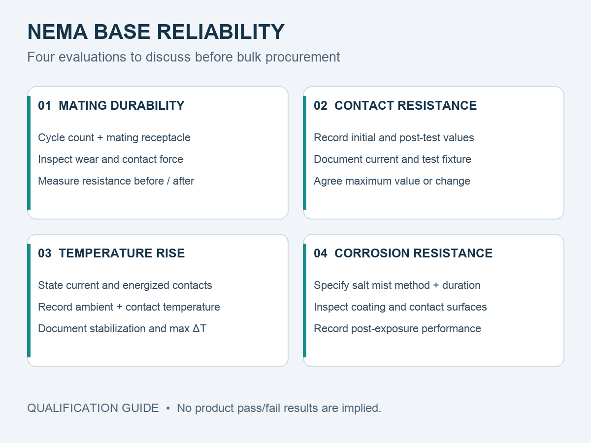
Quick answer. A NEMA photocontrol base is normally evaluated against four tests: mating and unmating durability, contact resistance, temperature rise under rated current, and salt spray or corrosion exposure. Each answers a different question, and none of them covers the others. The pass/fail judgement depends less on which tests were run than on whether the test conditions, the sample identity and the acceptance criteria were defined before testing — and whether the report records measured values rather than a single “passed” statement.
Which Reliability Tests Matter for NEMA Photocontrol Bases?
The four tests below appear repeatedly in OEM qualification programmes for lighting-control components. They are not the only tests a project may require, and the order in which they are listed is not a ranking of importance — a project that only ever sees one mating cycle still cares about corrosion, and a project in a dry climate still cares about spring force.
| Test | Test objective | Typical failure mechanism it exposes | Data to record | What the buyer must review |
|---|---|---|---|---|
| Mating and unmating durability | Confirm mechanical and electrical stability after repeated connection cycles | Spring deformation, loss of contact force, finish wear, locking-feature damage | Cycle count, mating receptacle used, resistance before and after, visual condition | Whether the cycle count matches your service model, and which receptacle was used |
| Contact resistance | Quantify the resistance added by the separable interface | Film growth, contamination, insufficient normal force | Method, test current, sample quantity, initial and post-condition values | Four-wire method, test current, and whether post-condition values exist |
| Temperature rise | Establish interface heating at rated current | Localised overheating, thermal runaway of contact resistance | Current, ambient, measuring points, stabilisation criterion, measured ΔT | Whether the current equals your load, and whether the mounting reflects real use |
| Salt spray / corrosion | Compare corrosion resistance of the finish system | Pitting, base-metal corrosion through porosity, resistance drift | Method and edition, duration, sample state, inspection criteria, post-test electrical values | Duration versus your environment, and whether electrical measurements were repeated |
Test 1 — Mating and Unmating Durability
Why Can Repeated Mating Damage Spring Contacts?
A spring contact works inside a narrow elastic window. Each insertion deflects it; each removal lets it return. As long as the deflection stays within the elastic range, the contact recovers its force. Two things break that assumption. First, over-deflection: if the base is forced onto a receptacle with tighter tolerances, or inserted at an angle, part of the deflection becomes permanent set and the spring no longer returns to its design force. Second, wear at the contact spot: sliding removes finish, and the debris generated by that wear can lodge in the interface.
The result is a slow loss of performance that is invisible on a new part. A base can pass a dimensional inspection and a first-article electrical check and still degrade faster than expected once it is installed and serviced a few times. This is why durability cycling is normally followed by a resistance measurement rather than a visual inspection alone — the interesting number is the resistance after cycling, not the appearance.
What Should Be Measured Before and After Cycling?
At minimum, contact resistance per contact before cycling, the same measurement after cycling, and a record of the mating receptacle used for the test. The receptacle matters because the interface is a pair: testing a base against a receptacle with different plating, different contact geometry or different tolerances produces a result that may not transfer to your assembly. If the report does not identify the mating part, the result cannot be reproduced.
Useful additions include contact force measurement before and after, visual or low-magnification inspection of the contact spots, and a note on whether the cycles were full insertions or partial movements. Vibration-induced micro-motion is a different loading case from a service technician removing a controller, and it produces a different failure mode.
Are 100 or 200 Mating Cycles Mandatory?
No — not as a general requirement that applies to every NEMA photocontrol base. Some OEM qualification programmes specify 100 or 200 cycles, and those numbers are perfectly reasonable as customer requirements for a given application. But they should not be presented as a mandatory cycle count imposed uniformly by ANSI C136.41 or by any other single document. Interface standards define mechanical, electrical and marking requirements for the control interface; they do not set one universal durability figure for every product configuration.
The correct framing is: your project defines the required cycle count, based on how often the controller will realistically be removed over its service life, plus margin. Then you ask the supplier to test to that number and report the result. A supplier who states “tested to 200 cycles” without telling you which standard required it, or which receptacle was used, has given you a number without a basis.
Test 2 — Contact Resistance
How Is Contact Resistance Evaluated?
The engineering-standard approach is a four-wire, or Kelvin, measurement. A current source drives a known current through the contact pair; a separate pair of voltage probes measures the drop across the interface. Because the voltage circuit carries almost no current, the resistance of the leads and probes does not enter the result. A two-wire measurement, by contrast, includes everything between the meter terminals and cannot be compared with a four-wire figure.
Test current also changes what is being measured. A dry-circuit measurement, taken at low current, characterises the interface film without heating it. A measurement at rated current includes the effect of that heating. Both are legitimate; they answer different questions and must not be mixed in a comparison table.
Why Do Initial and Post-Test Measurements Matter?
An initial value tells you the design starts in a good place. It says nothing about stability. The information a buyer actually needs is the delta: how much the resistance moved after cycling, after thermal exposure and after corrosion testing. A contact that starts at a low value and stays there is a different product from one that starts low and doubles after twenty cycles, even though both would pass a first-article inspection.
This is the single most common gap in supplier documentation: a report that contains initial values only. It is not dishonest, but it is incomplete for qualification purposes, and it should be recorded as such.
What Should a Contact Resistance Report Contain?
- Measurement method (four-wire or two-wire) and the instrument used
- Test current, and whether the measurement was dry-circuit or loaded
- Number of samples and how they were selected
- Probe locations — base side, receptacle side, or across the mated pair
- Conditioning applied before measurement (none, cycling, thermal, corrosion)
- Individual values per contact, not only an average
- The acceptance criterion the result is being judged against
No specific milliohm limit is quoted here, deliberately. The acceptable value depends on the contact design, the current it carries, the measurement method and the customer specification. A figure taken from an unrelated product and applied as a universal threshold is worse than no figure, because it creates false confidence.
Test 3 — Temperature Rise Under Rated Current
What Is Temperature Rise?
Temperature rise is the difference between the temperature measured at the contact (or at a defined point on the assembly) and the ambient temperature, once the assembly has reached thermal equilibrium at a specified current. It is a system measurement, not a material property: the same contact in free air and inside a sealed luminaire housing will not reach the same value.
Equilibrium is part of the definition. A reading taken before the temperature has stabilised understates the result, and a report should state the stabilisation criterion — for example, less than 1 K change over a defined period.
How Do Contact Resistance and Current Affect Heating?
Dissipation at the interface is the square of the current times the interface resistance, so the heating term grows faster than the load. Doubling current quadruples the dissipation at unchanged resistance, and a resistance increase compounds it. That is the mechanism behind the well-known failure pattern in which a connection that runs acceptably at commissioning drifts upward over months as its interface resistance slowly rises.
What Test Setup and Results Should Buyers Review?
Many OEM specifications use a temperature-rise limit in the region of 30 K above ambient at rated current. That is a common customer requirement, not a universal rule: applicability depends on the product configuration, the applicable standard and the ambient conditions specified. A report should be read against the requirement it was written for.
On the JL-241J specifically, the published datasheet lists a power interface rating of maximum 480 Vac, 50/60 Hz at 15 A rated loading, and a signal circuit rating of 0–30 Vdc at 250 mA maximum. Those are design ratings. They are not a measured temperature-rise result, and they should not be read as though every terminal in the base carries 15 A — the power contacts and the four dimming pins are different circuits with different ratings.
What to check in the setup: the current actually applied, the ambient temperature, where the thermocouples were placed, whether the test was run in free air or in a representative enclosure, the conductor size used to feed the sample, and the stabilisation criterion. A result reported without those details cannot be compared with another supplier’s result.
Test 4 — Salt Spray and Corrosion Resistance
Why Are Outdoor Electrical Contacts Exposed to Corrosion Risks?
A photocontrol sits at the top of a pole, in the weather, for a decade or more. It sees humidity cycling, condensation inside the luminaire, airborne chloride near coasts, sulfur compounds in industrial and urban atmospheres, and temperature cycling that repeatedly pulls moisture into and out of every crevice. The contact interface is the most vulnerable point in that assembly, because it is a small crevice by construction.
Corrosion at a contact does not have to be visible to matter. A thin film of corrosion product at the contact spot is enough to raise resistance, and by the time it is visible the interface has usually been degrading for some time.
How Is Salt Spray Testing Performed?
A salt mist test exposes samples to a controlled saline fog in a chamber for a defined period, at a defined concentration and temperature, after which the samples are inspected and, where specified, measured electrically. IEC 60068-2-11:2021 describes a salt mist test method for electrotechnical products, components and materials; its scope statement should be read before quoting it, because the method’s applicability and the interpretation of results depend on the product type and the agreed inspection criteria.
The details that determine whether a result is meaningful are almost all in the method statement: salt concentration, chamber temperature, whether the sample was energised, whether it was mated or unmated during exposure, how it was cleaned before inspection, and what counted as a failure.
What Do 48h, 96h or Longer Exposures Mean?
They mean that the samples survived that many hours of that particular test method. They do not translate into a number of years of outdoor service. A 96-hour test and a 480-hour test are different severity levels, and a longer exposure is generally a stronger filter, but neither is a service-life prediction.
Duration only becomes comparable when the method, the sample state and the inspection criteria are the same. Comparing “96 hours” from one supplier with “240 hours” from another, without knowing whether one test was run on plated coupons and the other on assembled and energised bases, is not a comparison at all.
Why Does Salt Spray Duration Not Equal Outdoor Service Life?
Because the chamber applies one aggressive condition continuously, while the field applies a mixture of conditions with different mechanisms. Real exposure includes drying cycles, pollution, UV, mechanical movement and electrical load — factors a continuous fog does not reproduce. Field life also depends on installation quality, drainage, and whether the assembly actually achieves the ingress protection it was designed for. Salt spray is best used as a comparative and screening tool between candidate finishes, and as a check that a process has not degraded, rather than as a life prediction.
How Should Buyers Read a Supplier Test Report?
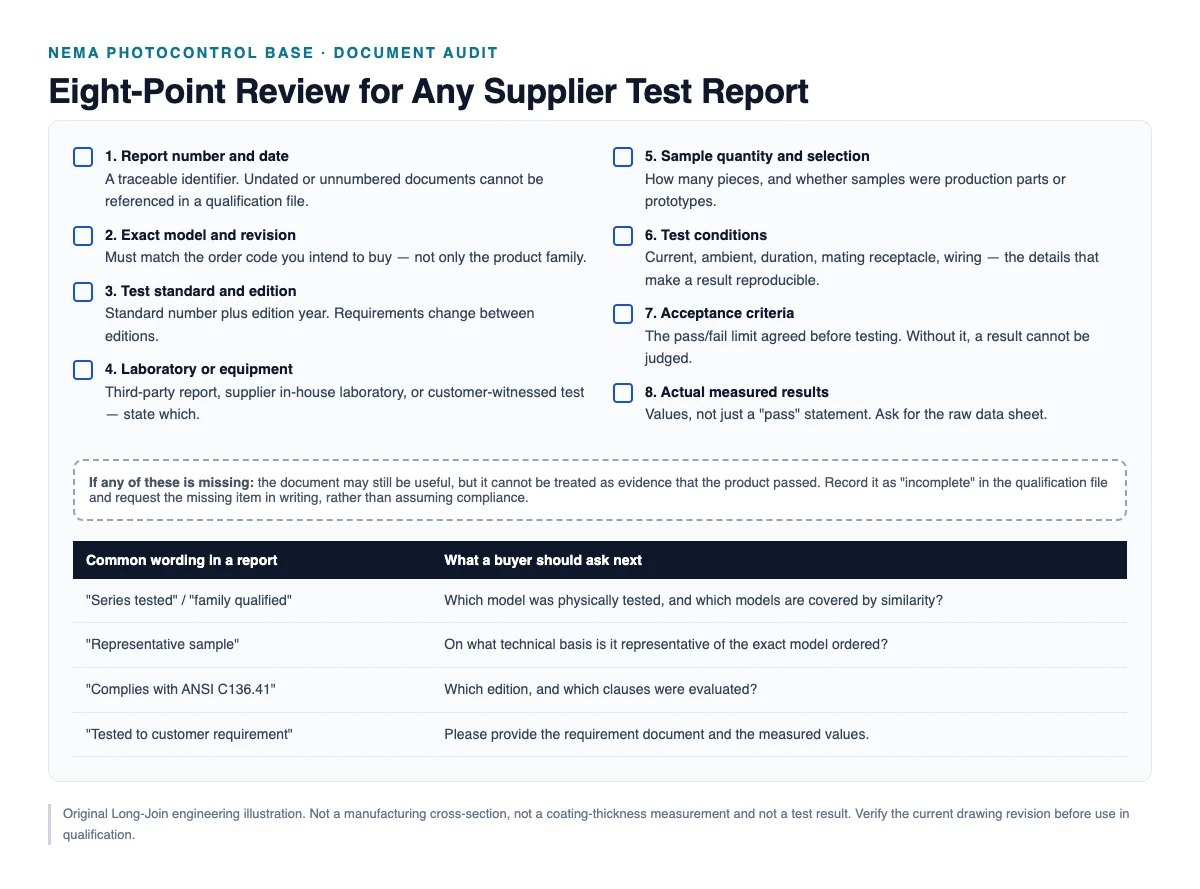
Eight elements determine whether a report can be used as qualification evidence. If any of them is missing, the document may still be informative, but it should be recorded as incomplete rather than treated as a pass.
| # | Element | Why it matters | If missing |
|---|---|---|---|
| 1 | Report number and issue date | Makes the document traceable and referenceable in your quality file | Cannot be cited in an approval record |
| 2 | Product model and revision | Confirms the tested item is what you will buy | Model scope is unproven |
| 3 | Test standard and edition | Requirements change between editions; the edition defines the method | Method cannot be reproduced |
| 4 | Laboratory or test equipment | Distinguishes third-party, in-house and customer-witnessed testing | Independence of the result is unknown |
| 5 | Sample quantity and source | Establishes whether results are from production parts or prototypes | Representativeness is unproven |
| 6 | Test conditions | Current, ambient, duration, receptacle, wiring — the variables that shape the outcome | Result cannot be compared with any other |
| 7 | Acceptance criteria | The limit against which pass/fail is judged | Pass/fail statement is unsupported |
| 8 | Actual measured results | Values, not a summary verdict | No data to trend or compare |
A useful habit is to read a report twice: once for the result, and once for what it does not cover. The second reading is where qualification decisions are actually made. Watch in particular for the phrase “series tested” or “family qualified” — it is legitimate practice, but it means one model was physically tested and others are covered by similarity. Ask which model was tested, and on what technical basis the similarity claim rests.
What Additional Tests May OEM Projects Require?
Depending on the application, an OEM may add requirements that are not part of a base-level qualification. These are project-specific, not universal requirements for all NEMA photocontrol bases:
- Material verification — confirmation of substrate alloy and finish by supplier certificate or, where risk justifies it, by third-party analysis.
- Dimensional inspection — critical interface dimensions against the drawing, with tolerances and gauge definition.
- Damp heat — steady-state or cyclic humidity exposure, often more relevant than salt spray for inland humid climates.
- Vibration and mechanical robustness — relevant where the controller is pole-mounted in a high-wind or high-traffic environment.
- Thermal cycling — combined temperature and load cycling, which stresses the interface differently from a steady-state rise test.
- Mating compatibility with the actual receptacle — testing the pair rather than the base alone.
Adding tests has a cost, and the cost should be justified by the risk it retires. A coastal municipal project and an inland industrial project do not need the same programme.
JL-241J: How to Request Product-Specific Qualification Evidence
Long-Join publishes the JL-241J material datasheet and an electrical assembly specification (revision 2405V2) covering the documented configuration, including PBT base material, a power interface rating of maximum 480 Vac at 15 A rated loading, a signal rating of 0–30 Vdc at 250 mA, and an operating range of −40 °C to +70 °C. What those documents establish is the design envelope. They are not a substitute for sample-specific test results on the four tests above.
The practical request to a supplier is therefore a document list, not a claim: for the exact order code, please provide the test reports covering mating durability, contact resistance (initial and post-condition), temperature rise at the rated current, and corrosion exposure — each with method, conditions, sample quantity, acceptance criteria and measured values.
Product and configuration information: JL-241J NEMA photocontrol base. Technical background on how contact resistance arises in the interface is covered in Why Do Contact Resistance and Plating Quality Matter in NEMA Photocontrol Bases?
To be explicit about the boundary: this article does not state that the JL-241J has passed any specific test for which a report has not been supplied. Where evidence has not been reviewed, the item is open.
Frequently Asked Questions
How many mating cycles should a NEMA base withstand?
There is no single mandated number for all products. 100 or 200 cycles are common customer qualification figures, but the appropriate value comes from your own service model — how often a controller is realistically removed and refitted over its life, with margin. Ask for the cycle count your specification requires, and ask which mating receptacle was used, because the interface is a pair.
How is contact resistance measured?
With a four-wire (Kelvin) measurement: a current is passed through the contact pair and the voltage drop is measured across the interface with separate probes, so lead resistance drops out. Test current, probe placement and sample conditioning all affect the reported value, so a figure without method detail is not comparable between suppliers.
What does a temperature-rise test demonstrate?
It shows how much the interface and surrounding assembly heat up above ambient at a defined current, once thermal equilibrium is reached. It demonstrates behaviour at that current, in that mounting arrangement. It does not by itself prove suitability at a higher current, in a different enclosure, or over a long service life.
Is 96-hour salt spray testing sufficient?
Sufficient for what depends on the environment and the purpose. As a screening check between candidate finishes it can be useful. As a prediction of coastal service life it is not — chamber exposure is a single continuous condition, while field exposure combines wetting and drying, pollution, load and movement. Treat duration as a severity indicator under a stated method, not as a lifetime.
Does UL Recognition cover every OEM test requirement?
No. Component recognition confirms that a component has been evaluated to applicable requirements under specified conditions of acceptability. It is not a statement that the component has met your particular durability, temperature-rise or corrosion criteria. Those must be evidenced by product-specific test reports that you review yourself. See UL Recognized vs. Reliability Tested for the scope distinction.
Key Takeaways
The four tests answer four different questions, and a passing result on one says almost nothing about the others. What makes a report usable is not the number of pages but the presence of eight specific elements: report identity, exact model and revision, standard and edition, laboratory, sample quantity, test conditions, acceptance criteria and measured values. Buyer requirements such as a cycle count or a temperature-rise limit are legitimate and should be written into the specification — but they should not be described as universal mandates of a standard. Salt spray duration is a severity indicator under a named method, never a service-life figure. Approve on product-specific data, record every gap as open, and test the base with the receptacle it will actually mate with.
Request a JL-241J qualification document review.
Tell us which tests your programme requires and the conditions behind them. We will respond with the documentation available for the exact configuration you intend to order, and identify clearly where evidence does not yet exist.
- Order code and pin configuration
- Required test list, with cycle counts and acceptance limits
- Rated current and ambient conditions
- Target market and environment
- Project timeline and expected annual volume
References and Technical Sources
- How to Evaluate the Reliability of a NEMA Photocontrol Base Before Bulk Purchasing — pillar guide.
- Long-Join JL-241J electrical assembly specification, rev. 2405V2 — published ratings used in this article.
- Long-Join JL-241J NEMA 7-pin material datasheet — materials and finishes.
- ANSI C136.41-2025 — interface requirements for external locking-type controls and luminaires.
- IEC 60068-2-11:2021, Environmental testing — Part 2-11: Tests — Test Ka: Salt mist — cited by designation and edition; read the published scope before applying it to a specific product type.
- UL Solutions — The UL Component Recognition Classification — definition of component recognition and conditions of acceptability.



One Response