OUTLINE
- Introduction
- Why Does ANSI Testing Target Specific Failure Modes?
- What Are the Six Common Failure Modes in ANSI C136.10 Testing?
- In Conclusion
ANSI C136.10 testing doesn’t just verify that a photocell works, it helps procurement teams, lighting engineers, and quality managers systematically expose the ways it can fail.
For evaluating photocell suppliers, understanding the failure modes that the standard targets is as important as understanding the passing criteria.
A supplier who knows where photocells fail is a supplier who has engineered against those failure points. It helps to learn about the most common failure modes identified during ANSI C136.10 testing, what causes each one, and why they matter for long-term outdoor lighting reliability.

Why Does ANSI Testing Target Specific Failure Modes?
Most failures that occur with photocells have typical patterns. ANSI C136.10 testing exists precisely because these patterns are predictable, and catching them in a lab is a lot cheaper than catching them on a pole.
The test isn’t just a pass/fail switch check. It puts the photocell through the kind of accumulated stress that only shows up after months or years in the field. It simulates stresses such as repeated switching cycles, surge events, temperature swings, and sustained water and dust exposure, to check for the cracks before the product ever reaches an installation.
What Are the Six Common Failure Modes in ANSI C136.10 Testing?
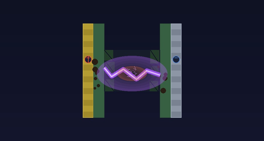
1. Contact Wear and Poor Contact

This is the most frequent failure mode in photocell relays, and it’s a direct consequence of the switching function the device performs throughout its service life.
What causes it:
- Every switching action creates a brief electrical arc at the relay contacts as they open and close under load
- Over thousands of cycles cause the contact surfaces to oxidise, pit, and burn
- As contact surface quality degrades, resistance across the junction increases
- In advanced cases, the contacts weld together (preventing the light from switching off) or fail to make contact at all (preventing it from switching on)
What testing looks for:
- Contact resistance measurements before and after lifecycle switching tests
- Visual inspection of contact surfaces for oxidation and pitting
- Zero-crossing technology, as used in the JL-207 series, significantly reduces arcing by switching the relay only when the AC waveform crosses zero voltage, which directly extends contact life
A photocell that passes contact wear testing has demonstrated its relay will maintain switching integrity across thousands of real-world cycles, not just on day one.
2. Mechanical Strength and Mechanism Fatigue

The physical mechanism that drives the switch open and closed is also subject to its own fatigue over time.
What causes it:
- Internal springs, actuators, and mechanical linkages are stressed on every switching cycle
- Material fatigue accumulates gradually, eventually causing components to crack, deform, or jam
- In bimetal designs, the thermal element itself can lose calibration after extended thermal cycling
What testing looks for:
- Full lifecycle switching tests at rated load and temperature
- Force and torque measurements on the twist-lock mechanism to confirm it engages and disengages within defined parameters throughout its service life
- Physical inspection for deformation, cracking, or loosening of internal components after test completion
Mechanical fatigue failures are difficult to predict without testing because they accumulate invisibly. A photocell that looks and functions correctly at 1,000 cycles may jam at 8,000. Lifecycle testing closes that gap.
3. Electrical Insulation Breakdown or Leakage
Photocells operate at mains voltage in outdoor environments, a combination that makes insulation integrity a safety-critical requirement, not just a performance one.
What causes it:
- Prolonged exposure to high-voltage stress gradually degrades insulation materials
- Moisture ingress accelerates degradation by providing a conductive path for leakage current
- Thermal cycling causes insulation materials to expand and contract, eventually cracking at stress points
- Manufacturing defects in insulation thickness or material quality create weak points that fail under sustained voltage
What testing looks for:
- Dielectric withstand (hi-pot) testing applies a voltage significantly higher than the rated operating voltage across the insulation to verify that no breakdown occurs
- Insulation resistance measurement confirms leakage current stays within safe limits
- Testing is conducted both at ambient temperature and at elevated temperature to simulate worst-case operating conditions
Insulation failure in a street-mounted photocell creates a shock hazard and a risk of fire. This is a safety failure, not just a performance failure, and it is non-negotiable in any photocell intended for public infrastructure.
4. Surge Current Damage
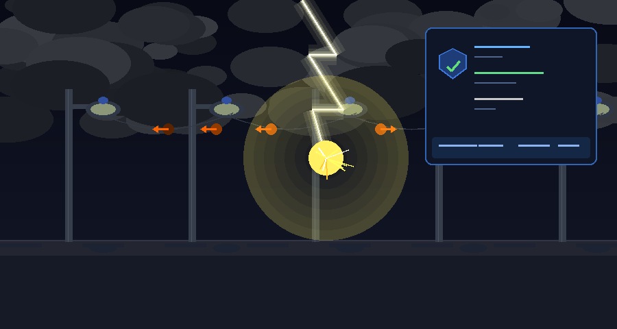
Lightning strikes and grid switching transients generate voltage spikes that can reach several thousand volts in milliseconds, far beyond what unprotected photocell components can survive.
What causes it:
- Lightning induces transient voltages in power lines and connected equipment through both direct strikes and electromagnetic induction from nearby strikes
- Grid switching events, such as capacitor banks, large motor startups, and utility switching, generate voltage transients that travel along supply lines
- Without adequate surge protection, these transients destroy the photocell’s switching components, sensor circuit, or both in a single event
What testing looks for:
- Surge immunity testing applies defined voltage and current waveforms to verify that the photocell survives without damage or functional degradation
- MOV (Metal Oxide Varistor) performance is evaluated for clamping voltage accuracy and energy absorption capacity
Surge damage is instantaneous and total. A photocell without adequate surge protection may pass every other test and still fail in service the first time a significant transient event occurs on the supply network.
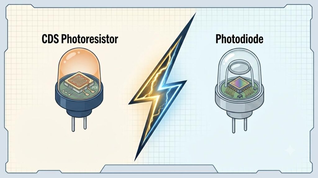
5. Failure or Drift of Photosensitive Devices
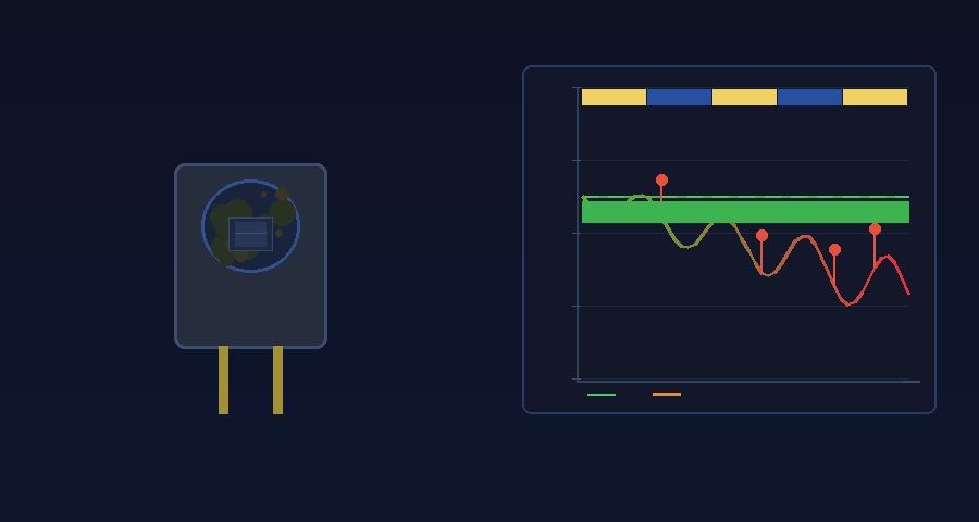
The photosensitive component of a photocell is the core sensing element. If it drifts or becomes unstable, the photocell’s switching behaviour becomes unreliable regardless of how well the relay performs.
What causes it:
- Prolonged UV exposure degrades photoresistor materials, causing sensitivity to drift over time
- Temperature cycling affects the electrical characteristics of phototransistors, shifting the lux threshold at which switching occurs
- Contamination of the sensor lens by external factors such as dust, road film, and insect residue reduces effective sensitivity and can cause the photocell to switch on prematurely or fail to switch off at dawn
What testing looks for:
- Sensitivity measurements at defined lux levels before and after environmental stress tests
- UV exposure testing to simulate long-term outdoor operation
- Temperature coefficient testing to confirm switching threshold stability across the rated operating range
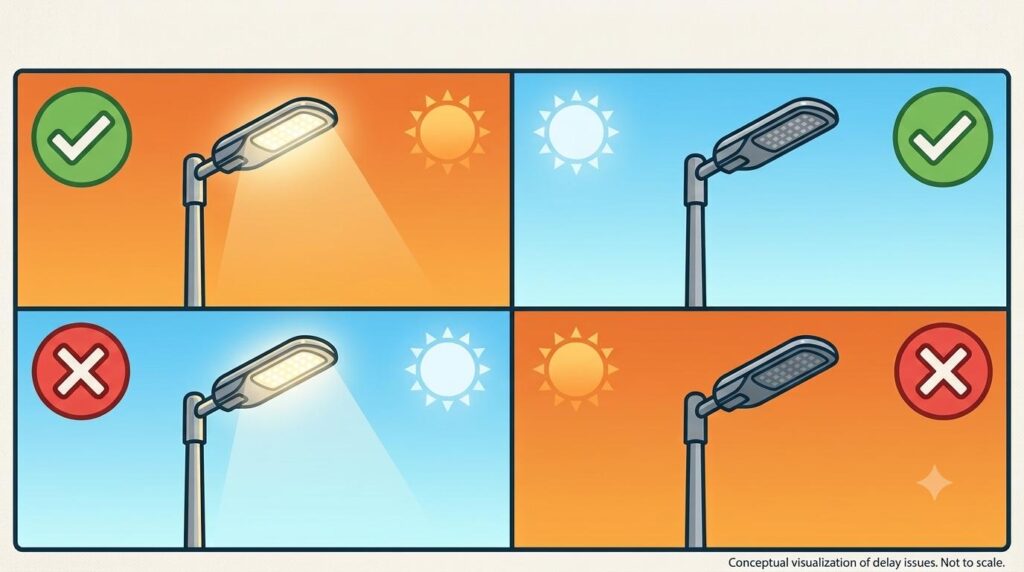
A photocell with a drifting sensor doesn’t fail visibly, it just starts switching at the wrong times. Lights come on too early, stay on past dawn, or flicker in complex light environments. These are chronic service issues that are difficult to diagnose and expensive to address across a large installed fleet.
6. Failure of Environmental Protection
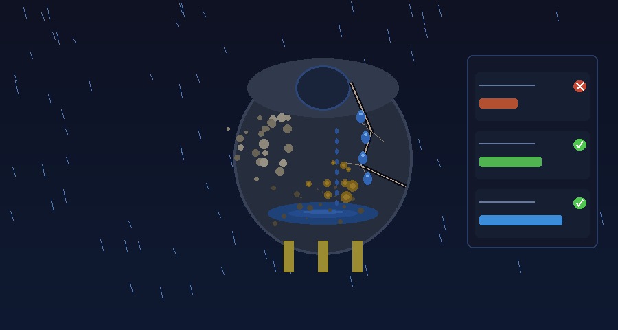
All the electrical and mechanical performance in the world counts for nothing if dust and moisture can enter the photocell housing and destroy the internal components.
What causes it:
- The sealing gasket loses elasticity over time due to UV exposure and thermal cycling, creating gaps that allow ingress
- UV exposure causes polycarbonate and other housing materials to become brittle and crack, breaking the seal
- Cable entry points are a common ingress path if the seal around wire entries is not properly designed and maintained
- Units with IP54 or lower are vulnerable to direct water jet exposure in wind-driven rain conditions
What testing looks for:
- IP65 dust ingress testing: talcum powder test in a sealed chamber confirms no particles enter the housing under negative pressure
- IP65 water ingress testing: water jets at 12.5 litres per minute from all angles for a minimum of 3 minutes, with no water entry permitted
- Post-test inspection of internal components for moisture, condensation, or dust contamination
- Gasket and housing material assessments after UV and thermal ageing tests
Environmental ingress failure is the leading cause of premature photocell failure in outdoor installations. A single moisture ingress event can cause internal corrosion, short circuits, or component failure that ends the photocell’s service life years before its rated lifecycle.
In Conclusion
ANSI C136.10 testing is not a formality; it is a systematic attempt to find the six ways a photocell is most likely to fail before it does so in the field. These represent real failure paths that end photocell service life prematurely in outdoor lighting installations worldwide. Photocells, such as those in Chi-Swear’s product range, that have been rigorously tested against all six and passed, are photocells that have been engineered with those failure modes in mind from the start.